


47
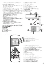
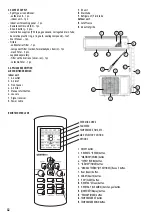
INDOOR UNIT LOCATION SELECTION
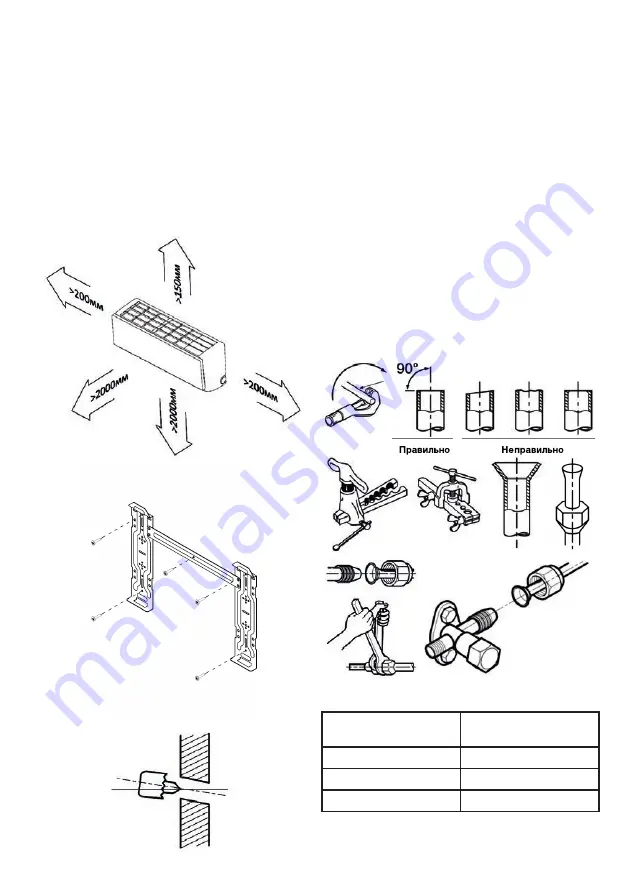
Select a location where the surface can support the weight and
vibration of the indoor unit. There should be a sufficient free space
for the installation and subsequent maintenance of the indoor unit.
There should be enough free space in order not to restrict air
circulation and no obstructions on the air discharge side. The
indoor unit should be located at least 1 meter away from radio or TV
receivers in order to minimize the probability of sound and picture
distortion during operation. The impact of direct sunlight and other
heat sources should be minimized. The indoor unit should be installed
perfectly level. The mounting bracket of the indoor unit should be
securely fastened.
INDOOR UNIT MOUNTING DIMENSIONS
MAKING THE HOLE IN THE WALL
Select the location for the wall hole.
Before drilling the hole make sure that there are no embedded
electrical cables or pipelines inside the wall.
Drill a hole, 60 to 80 mm in diameter, at a slight angle towards the
outdoor unit. Insert a liner if necessary.
CONNECTING INTER
-
UNIT ELECTRIC CABLE AND POWER SUPPLY CABLE
Refrigerant Tube Flaring
Properly cut the copper tube of the required length with a tube cutter.
Remove all burrs from the cut edge of the tube. When deburring the
cut hold the tube with the cut end facing down to prevent metal
shavings from getting inside the tube. Put a tapered ring nut of the
proper size on the tube. Be careful as you will not be able to install
the ring nut after flaring the tube end. Flare the tube end using a
specialized tool and observing all required procedures relevant for
this type of work. Check the resulting flare, it should have the same
length and a smooth edge around the whole circumference and a
shiny inner surface without scratches. If the flare is defective, cut the
flared end away and repeat the flaring process.
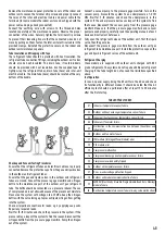
Refrigerant Tube Connection
Align the pipelines and tighten the tapered ring nut by hand to a stop.
Hold the nozzle from rotating with a spanner and tighten the ring
nut with a torque wrench, observing the torque specified in the table.
I
Table 2
Tube size
(mm)
Torque
(N, m)
φ 6.35 (1/4”)
15~25
φ 9.52 (3/8”)
35~40
φ 12.70 (1/2”)
45~60


