IOM-HP-S-DIFF
5
5. Clean debris from within the regulator body
(1) cav i ty. Make certain the old cylinder gas ket
(18) is cleaned out of the body (1) recess.
Clean all parts to be reused according to
owner's procedures.
6. Reinstall a new cylinder gasket (18). Press
firmly and evenly into place using the cyl in der
(16). Do not use a “homemade” cylinder
gas ket. Pipe seal ant may be lightly coated to
the gasket (18) surfaces prior to installation.
In spect to see that cylinder gasket (18) is
com plete ly pressed into place and cylinder
(16) is cen tered with body cap (5) opening.
7. Install a new back up ring (27) and quad ring
(26) on piston (15). Make certain the teflon
back up ring (27) will insert the body cap (5)
first, before the quad ring (26) (See Figure 3).
Make sure the quad ring (26) is on straight with
no twist
.
Use a good grade lightweight grease
on both ring seals (26,27). Slide piston (15)
into cyl in der (16).
8. Place piston spring (17) into the cavity of the
piston (15).
9. Insert new body cap o-ring (25) into groove of
body cap (5). Use a good grade lightweight
grease on body cap o-ring (25). Use pipe
thread seal ant ap plied to the body cap (5)
threads. Screw body cap (5) into body (1).
Impact until body cap (5) is metal to metal
against body (1) at the body cap (5) shoulder.
D. Bench test for suitable operation
(Test Fluid:
Air or compressed gas).
NOTE:
Reg u la tors are not tight shutoff devices.
Even if pres sure builds up beyond setpoint, a
reg u la tor may or may not develop tight shutoff.
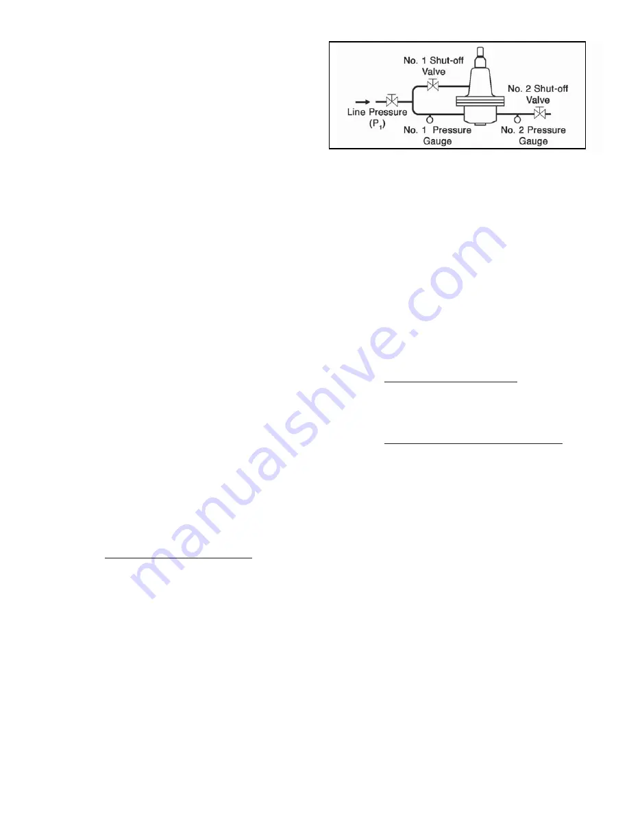
1. Check for internal trim leakage: With No.
1 shut-off valve closed and No. 2 shut-off
valve cracked open, turn on inlet op er at ing
pres sure. Fol low in struc tions from SEC TION
IV-2.
and set a differential pres sure of 20
psig (1.4 Barg) in the down stream line (No.
2 Gauge). Close No. 2 shut-off valve and
check for tight shutoff.
NOTE:
Seat leakage
not to exceed 15 bub bles per minute. Do
not allow ex ces sive build up if seat leak age
ex ists (crack open No. 2 shut-off valve to
pre vent build up)
. If seat leak age is ex ces sive,
pro ceed with the fol low ing steps to de ter mine
location of leak:
a. Close No. 1 shut-off Valve.
b. Turn off inlet operating pressure (P
1
).
c.
Re
move entire topworks per SEC TION
VI-B., steps 1-5.
d. Turn inlet operating pressure (P
1
) on.
e. Spray liquid leak detector in the space
be tween cylinder (16) and body (1) to
check for cylinder gasket (18) leakage.
f. Pour a few drops into recess along pis ton
post (15) to check for seat leakage.
g. Fill the recess to check for quad ring (26)
leakage.
Once location of leak is detected, proceed
to SECTION VII-6 for Cause/Remedy and
SECTION VI-C. for internal trim replacement.
After leak is remedied, proceed to SEC TION
VI-B., steps 8-15 to re as sem ble top works.
2. Check regulator performance: With Step No.
1 con di tions met, open and close No. 2 shut-
off valve to check reg u la tor's per for mance for
smooth ness and re peat abil i ty.
3. Proof test to check for external leakage:
a. Build inlet pres sure to 1-1/2 times
max i mum out let pres sure; but not to
exceed 1-1/2 times the Max. Out let and
Spring Cham ber Pressure Rat ing (See
HP-S-DIFF TB, Ta ble 2). Close No. 2 shut-
off valve and crack open No. 1 shut-off
valve until full inlet pressure exists in the
spring cham ber (2) and down stream line
(No. 2 gauge will reg is ter same pres sure
as No. 1 gauge).
b. Spray the entire regulator with a liquid leak
detector and visually inspect for external
leak age. Repair unit if leak is detected.
See SEC TION VI MAINTENANCE.
c. To relieve all pressures simultaneously
(pre vent ing diaphragm (12) damage
due to ex ces sive
∆
P across diaphragm
(12)), crack open No. 2 shut-off valve and
shut off inlet pres sure. This will uniformly
bleed off all pres sure con tained within the
reg u la tor.
4. Return to Section II for Installation and Sec tion
IV for Startup.
Figure 2:
Recommended Bench Test
Piping Schematic for HP-1+6+S


