IOM-HP-S-DIFF
3
6.
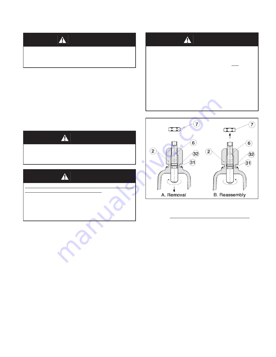
Adjusting screw (6) o-ring inspection
:
a. With locknut (7) and closing cap (28)
re moved, turn adjusting screw (6) CW
as far as possible by turning flats on
top end. Care ful ly reach inside spring
cham ber (2) and grasp ad just ing screw
(6) by hand.
NOTE:
For 1/2" (DN15)
and 3/4" (DN20) size reg u la tors a small
piece of plastic tubing with a 3/4" (19 mm)
inside di am e ter may be used to grasp the
ad just ing screw (6).
Complete ad just ing
screw (6) removal by ro tat ing CCW. See
Figure 1.
b. Inspect the backup ring (32) and quad ring
(31) for wear. If nicked or torn - replace.
NOTE:
Make certain the Teflon backup
ring (32) will insert into spring cham ber (2)
before the quad ring (31). (See Fig ure 3
blow-up illustration). Make sure the quad
ring (31) is on straight with no twist. Use
a good grade light weight grease on both
ring seals (31,32).
A. General:
1. Maintenance procedures hereinafter are
based upon re mov al of the regulator unit from
the pipeline where in stalled.
2. Owner should refer to owner's procedures for
removal, handling, cleaning and dis pos al of
nonreusable parts, i.e. gaskets, etc.
3. Refer to Figure 3 for view of regulator.
WARNING
SPRING UNDER COMPRESSION. Relieve spring
compression prior to re mov ing diaphragm flange bolts.
Fail ure to do so may result in flying parts that could cause
per son al injury.
CAUTION
DO NOT AT TEMPT TO REMOVE ADJUSTING SCREW (6)
FROM TOP OF SPRING CHAM BER (2). The ad just ing
screw (6) is threaded upward from inside the spring
chamber (2). The CCW ro ta tion used to relieve range
spring (14) tension will come to a stop. At the stop ping
point, do not apply any torque to ad just ing screw (6) or
dam age may occur and ren der the unit in op er a ble.
See
Figure 1.
CAUTION
When body flange hardware (9,23,34,35) is re moved
from this unit it should al ways be replaced with new.
The new hardware (9,23,34,35) must have the prop er
grade spec i fi ca tion iden ti fi ca tion markings and meet the
following standards:
1. All cap screws (23) and flange stud nuts (9) must have
"heavy hex heads".
2. All studs (34,35) and cap screws (23) must comply with
or exceed the requirements of ASTM A-193, Grade B7.
3. All flange stud nuts (9) must comply with or exceed
the requirements of ASTM A-194, Grade 2H.
New body flange hardware (9,23,34,35) may be pur chased
from Cashco, Inc. or through the OEM.
Figure 1:
Adjusting screw (6) o-ring inspection.
B. Diaphragm Replacement:
1. Securely install the body (1) in a vise with the
spring chamber (2) directed upwards.
2. To relieve range spring (14) compression,
re move clos ing cap (28) by turning CCW.
Re move lock nut (7) by turning CCW. Turn
ad just ing screw (6) CCW until range spring
(14) compression is relieved.
NOTE: See
CAUTION C)
.
3. Draw or embed a match mark between body
(1) casting, body spacer (24), and spring
cham ber (2) casting along flanged area.
4. Remove all body flange hardware (9,23,34,35).
5. Remove spring chamber (2), range spring
(14), spring button (4), pressure plate (3), body
spacer (24), diaphragm (12), and o-rings (30).
WARNING
SYSTEM UN DER PRES SURE. Prior to per form ing any
maintenance, isolate the reg u la tor from the system and
relieve all pres sure. Failure to do so could result in
personal injury.
SECTION VI
VI. MAINTENANCE


