65
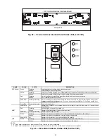
DPI Communications Interface Board
Status LEDs
Fig. 68 — Communications Interface Board Status LEDs (LF-2 VFD)
a23-1592
2
8
5
7
9
1
3
4
6
Allen-Bradley
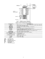
Fig. 69 — Drive Status Indicator Status LEDs (Std Tier VFD)
a19-1815
NOTES:
1. A Type 1 alarm indicates that a condition exists. Type 1 alarms are user configurable.
2. A Type 2 alarm indicates that a configuration error exists and the drive cannot be started. Type 2 alarms are not configurable.
NAME
COLOR
STATE
DESCRIPTION
STS (Status)
Green
Flashing
Drive ready but not running, and no faults are present.
Steady
Drive running, no faults are present.
Yellow
Flashing
Drive is not running. A type 2 (non-configurable) alarm condition exists and the drive cannot be started.
Steady
Drive is not running, a type 1 alarm condition exists. The drive can be started.
Red
Flashing
A major fault has occurred. Drive cannot be started until fault condition is cleared.
Steady
A non-resettable fault has occurred.
Red/Yellow
Flashing Alternately
A minor fault has occurred. When running, the drive continues to run. System is brought to a stop under
system control. Fault must be cleared to continue. Use parameter 950 [Minor Flt Config] to enable. If not
enabled, acts like a major fault.
Green/Red
Flashing Alternately
Drive is flash updating.
ENET
None (Unlit)
Off
Adapter and/or network is not powered, adapter is not properly connected to the network, or adapter needs
an IP address.
Red
Flashing
An EtherNet/IP connection has timed out.
Steady
Adapter failed the duplicate IP address detection test.
Red/Green
Flashing Alternately
Adapter is performing a self-test.
Green
Flashing
Adapter is properly connected but is not communicating with any devices on the network.
Steady
Adapter is properly connected and communicating on the network.
LINK
None (Unlit)
Off
Adapter is not powered or is not transmitting on the network.
Green
Flashing
Adapter is properly connected and transmitting data packets on the network.
Steady
Adapter is properly connected but is not transmitting on the network.
Содержание EVERGREEN 23XRV
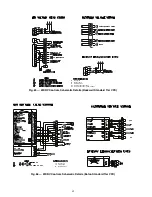
Страница 53: ...53 Fig 60 Typical Field Wiring Schematic LF 2 VFD Shown NOTE See Notes for Fig 60 on page 56 ...
Страница 54: ...54 Fig 60 Typical Field Wiring Schematic LF 2 VFD Shown cont a23 1585 ...
Страница 55: ...55 Fig 60 Typical Field Wiring Schematic LF 2 VFD Shown cont a23 1586 ...
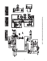
Страница 60: ...60 Fig 63 23XRV Controls Schematic LF 2 ...
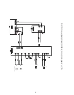
Страница 63: ...63 SEE NEXT PAGE SEE NEXT PAGE SEE NEXT PAGE Fig 67 23XRV Controls Schematic Rockwell Standard Tier VFD Shown ...
Страница 64: ...64 FROM PREVIOUS PAGE Fig 67 23XRV Controls Schematic Rockwell Standard Tier VFD Shown cont ...
Страница 73: ...73 Fig 78 Lead Lag Control Wiring Parallel Flow Application Unit with R Compressor Shown a23 1597 ...
Страница 74: ...74 Fig 79 Lead Lag Control Wiring Series Flow Application Unit with R Compressor Shown a23 1598 ...


