


59
WIRING THE FIELD WIRING TERMINAL STRIPS FOR
LF-2 VFD — This section describes how to wire the field wir-
ing terminal strips shown in Fig. 63-68. The control terminal
blocks are mounted to the inside of the enclosure, above and
below the control panel.
NOTE: Up to 30 v may be measured across open contact
terminals on the hazardous voltage terminal strip.
1. Turn off, lock out, and tag the input power to the drive.
Wait five minutes.
2. Verify that there is no voltage at the input terminals (L1,
L2, and L3) of the power module.
3. Verify that the status LEDs on the communications
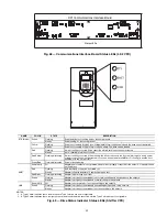
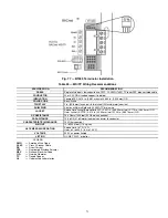
interface board are not lit. See Fig. 69. The location of the
communications interface board is shown in Fig. 10.
4. Use a screwdriver to remove conduit twist outs in the
control panel. Do not punch holes or drill into the top
surface of the control center enclosure for field wiring.
Knockouts are provided in the back of the control center
for field wiring connections.
5. Connect the control wiring as shown in Fig. 61. Tighten
all connections to 7 to 9 in.-lb.
WIRING THE FIELD WIRING TERMINAL STRIPS FOR
STD TIER VFD — This section describes how to wire the
field wiring terminal strips shown in Fig. 65-67. The control
terminal blocks are mounted to the inside of the enclosure, on
the right side.
NOTE: Up to 30 v may be measured across open contact
terminals on the voltage terminal strip.
1. Turn off, lock out, and tag the input power to the drive.
Wait five minutes.
2. Verify that there is no voltage at the input terminals (L1,
L2, and L3) of the power module.
3. Verify that the keypad and drive status indicators
(Fig. 69) are not lit. The location of the drive status indi-
cator is shown in Fig. 11.
4. Mount incoming wiring using the knockouts on the panel.
Do not drill holes into the top side of the enclosure.
5. Connect the control wiring as shown in Fig. 67. Tighten
all connections to 7 to 9 in.-lb.
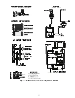
CONNECT CONTROL INPUTS — Wiring may be speci-
fied for a spare safety switch, and a remote start/stop contact
can be wired to the starter terminal strip. Additional spare sen-
sors and Carrier Comfort Network
®
modules may be specified
as well. These are wired to the machine control panel as
indicated in Fig. 70.
CONNECT CONTROL OUTPUTS — Connect auxiliary
equipment, chilled and condenser water pumps, and spare
alarms as required and indicated on job wiring drawings.
CONNECT STARTER — The 23XRV chiller is equipped
with a unit-mounted VFD starter (Fig. 71).
Remove the VFD shipping bracket shown in Fig. 22 for
typical installations. For seismic units, do not remove the ship-
ping bracket.
IMPORTANT: Be sure to ground the power circuit in accor-
dance with the National Electrical Code (NEC), applicable
local codes, and job wiring diagrams. Also, make sure cor-
rect phasing is observed for proper rotation.
CAUTION
Do not punch holes or drill into the top surface of the
control center. Knockouts are provided in the back of the
control center for wiring connections.
Содержание EVERGREEN 23XRV
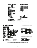
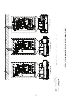
Страница 53: ...53 Fig 60 Typical Field Wiring Schematic LF 2 VFD Shown NOTE See Notes for Fig 60 on page 56 ...
Страница 54: ...54 Fig 60 Typical Field Wiring Schematic LF 2 VFD Shown cont a23 1585 ...
Страница 55: ...55 Fig 60 Typical Field Wiring Schematic LF 2 VFD Shown cont a23 1586 ...
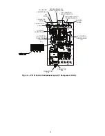
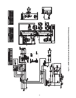
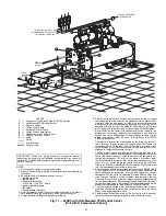
Страница 60: ...60 Fig 63 23XRV Controls Schematic LF 2 ...
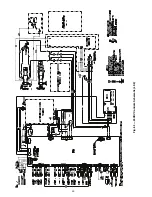
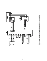
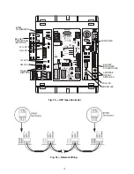
Страница 63: ...63 SEE NEXT PAGE SEE NEXT PAGE SEE NEXT PAGE Fig 67 23XRV Controls Schematic Rockwell Standard Tier VFD Shown ...
Страница 64: ...64 FROM PREVIOUS PAGE Fig 67 23XRV Controls Schematic Rockwell Standard Tier VFD Shown cont ...
Страница 73: ...73 Fig 78 Lead Lag Control Wiring Parallel Flow Application Unit with R Compressor Shown a23 1597 ...
Страница 74: ...74 Fig 79 Lead Lag Control Wiring Series Flow Application Unit with R Compressor Shown a23 1598 ...


