49
INSTALL VENT PIPING TO RELIEF VALVES —
The 23XRV chiller is factory equipped with relief valves on
the cooler and condenser shells. Refer to Fig. 59 and Table 21
for size and location of relief devices. Vent relief devices to the
outdoors in accordance with ANSI/ASHRAE 15 (latest
edition) Safety Code for Mechanical Refrigeration and all
other applicable codes.
1. Dual pressure relief valves are mounted on the three-way
valves in some locations to allow testing and repair with-
out transferring the refrigerant charge. Three-way valve
shafts should be turned either fully clockwise or fully
counterclockwise so only one relief valve is exposed to
refrigerant pressure at a time.
The flow area of discharge piping routed from more than
one relief valve, or more than one heat exchanger, must
be greater than the sum of the outlet areas of all relief
valves that are expected to discharge simultaneously. All
relief valves within a machinery room that are exposed to
refrigerant may discharge simultaneously in the event of a
fire. Discharge piping should lead to the point of final
release as directly as possible with consideration of pres-
sure drop in all sections downstream of the relief valves.
2. Provide a pipe plug near outlet side of each relief device
for leak testing. Provide pipe fittings that allow vent
piping to be disconnected periodically for inspection of
valve mechanism.
3. Piping to relief devices must not apply stress to the
device. Adequately support piping. A length of flexible
tubing or piping near the relief device is essential on
spring-isolated machines.
4. Cover the outdoor vent with a rain cap and place a
condensation drain at the low point in the vent piping to
prevent water build-up on the atmospheric side of the
relief device.
COOLER
CONTROL CENTER
COOLER REFRIGERANT
PUMPOUT VALVE
COOLER INLET
I
S
OLATION VALVE
COOLER CHARGING
VALVE
CONDEN
S
ER
CHARGING
VALVE
DI
S
CHARGE I
S
OLATION
VALVE (OPTIONAL)
OIL
S
EPARATOR
PUMPOUT
CONDEN
S
ER
WATER
S
UPPLY
AND RETURN
PUMPOUT
CONDEN
S
ER
2
3
4
5
PRE
SS
URE
RELIEF
S
AFETY
VALVE
PUMPOUT
COMPRE
SS
OR
S
ERVICE VALVE
1
a
S
ERVICE VALVE ON
PUMPOUT UNIT
=
S
ERVICE VALVE ON
CHILLER
=
7
1
a
1
b
11
Fig. 57 — Optional Pumpout System Piping Schematic without Storage Tank — Configured to Store
Refrigerant in Cooler or Condenser (Unit with R Compressor Shown)
a23-1545
COMPRESSOR
OIL
SEPARATOR
CONDENSER
LEAVING
WATER
ENTERING
WATER
VALVE
5
VALVE
4
VALVE
2
CONTROL
PANEL
FRAME
ASSEMBLY
OIL
HEATER
VALVE
3
OIL FILL
FITTING
Fig. 58 — Pumpout Unit
a23-1546
DANGER
Refrigerant discharged into confined spaces can displace
oxygen and cause asphyxiation.
Содержание EVERGREEN 23XRV
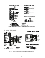
Страница 53: ...53 Fig 60 Typical Field Wiring Schematic LF 2 VFD Shown NOTE See Notes for Fig 60 on page 56 ...
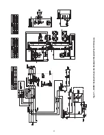
Страница 54: ...54 Fig 60 Typical Field Wiring Schematic LF 2 VFD Shown cont a23 1585 ...
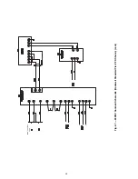
Страница 55: ...55 Fig 60 Typical Field Wiring Schematic LF 2 VFD Shown cont a23 1586 ...
Страница 60: ...60 Fig 63 23XRV Controls Schematic LF 2 ...
Страница 63: ...63 SEE NEXT PAGE SEE NEXT PAGE SEE NEXT PAGE Fig 67 23XRV Controls Schematic Rockwell Standard Tier VFD Shown ...
Страница 64: ...64 FROM PREVIOUS PAGE Fig 67 23XRV Controls Schematic Rockwell Standard Tier VFD Shown cont ...
Страница 73: ...73 Fig 78 Lead Lag Control Wiring Parallel Flow Application Unit with R Compressor Shown a23 1597 ...
Страница 74: ...74 Fig 79 Lead Lag Control Wiring Series Flow Application Unit with R Compressor Shown a23 1598 ...


