


Ductable air-cooled scroll
chillers and heat pumps
16
Minimum installation volume
The electronic control for these units incorporates an auto-adaptive
control for the compressor operating time based on the time set for
anti-short-cycle.
This control reduces the number of times the compressor is started
up and permanently adjusts the system's thermal inertia, favouring
the reduction of the minimum volume of water in the installation. The
size of the buffer tank can also be decreased since the unit will be
stopped for less time.
Where:
V
inst
Installation volume (l)
V
inst
Expansion vessel volume (l)
V
1
Initial volume of 1kg of water (at water temperature with the machine stopped)
V
2
Final volume of 1kg of water (at water temp. with the machine at normal speed)
P
f
Final network pressure (safety valve pressure in bars + 1)
P
i
Initial network pressure (absolute
fi
lling pressure of the installation in bars)
Note:
If the hydraulic circuit has a buffer tank, its volume must be taken
into account for this calculation.
• Volume occupied by 1kg of water at different temperatures:
Maximum installation volume
The water capacity for the installation obtained from this equation
corresponds to the maximum that
the installation allows based on the
expansion vessel assembled.
Installation water volume
Temperature (ºC) Volume (l)
Temperature (ºC) Volume (l)
0
1,00013
50
1,0121
4
1,00000
60
1,0171
10
1,00027
70
1,0227
20
1,00177
80
1,0290
30
1,00435
90
1,0359
40
1,00782
100
1,0434
f
i
f
vessel
INST
P
V
V
P
P
V
V
⋅
−
−
⋅
)
(
)
(
1
2
=
The calculation of the minimum water volume has been done for nominal
EUROVENT conditions, only in cooling mode. This value is applicable
for the majority of refrigeration applications (group with fan-coil units).
Note
: The buffer tank is indispensable in installations that operate with a
reduced volume of water (group with an air handling unit) or for industrial
processes. For applications with a heat pump, it is recommended that
the buffer tank be used in order to maintain a stable temperature during
the defrosting cycles.
Hydraulic connections
30PA/PH/
PAC/PHC
Minimum
volume (I)
Minimum
fl
ow (m
3
/h)
Maximum
fl
ow (m
3
/h)
90STD
101
2,2
6,2
100STD
120
2,7
7,4
120STD
143
3,1
8,8
160STD
187
4,1
11,3
180STD
204
4,3
12,7
90HEE
107
2,1
6,7
100HEE
132
2,9
8,1
120HEE
152
3,3
9,5
160HEE
189
3,7
11,7
180HEE
210
4,0
12,8
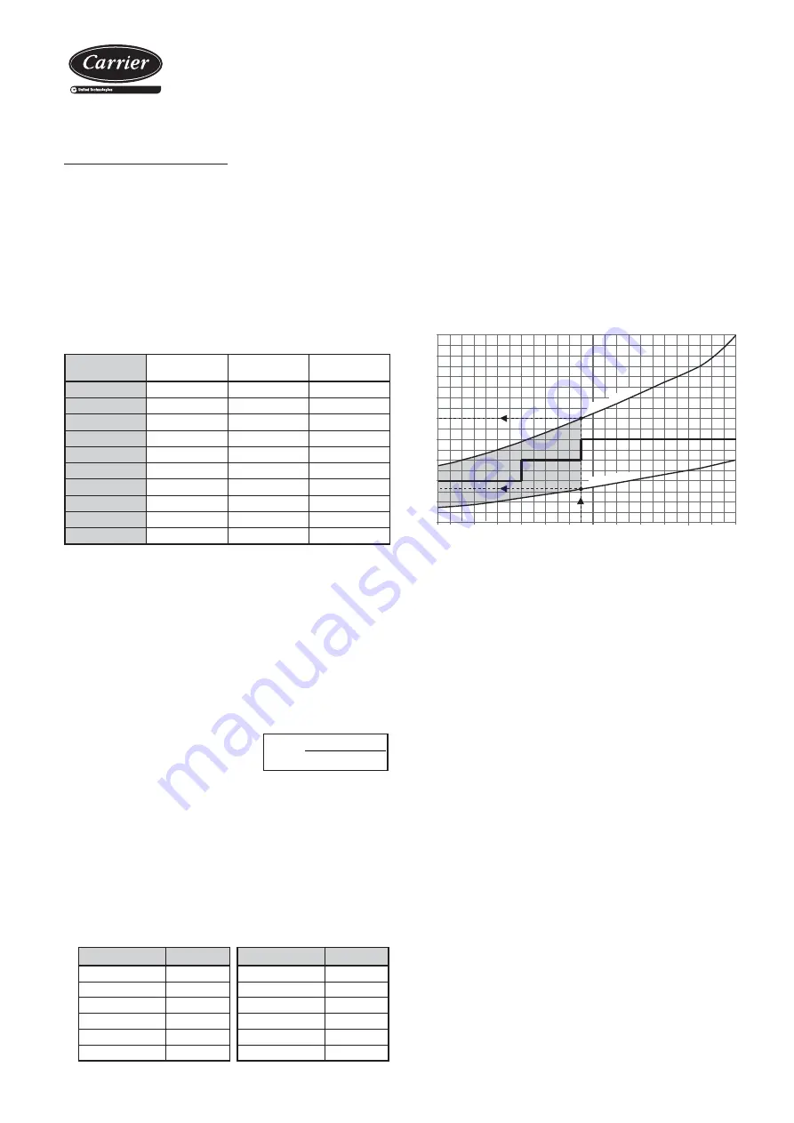
Evaporator operating limits
The curves represent the minimum and maximum admissible
temperature increases based on the outlet (discharge) temperature,
for both pure water and glycol water.
For temperature changes that are not listed between the curves, please
consult.
The minimum outlet temperature for the unit will be +5ºC with pure
water and -7ºC with glycol water.
•
Example
For an outlet water temperature of +5ºC:
Minimum
temp.: 2,6ºC
T. condition 7,6ºC / 5ºC
Maximum
temp.: 6,0ºC
T. condition
11ºC / 5ºC
Anti-freeze protection with glycol water
If a pure product is used for dilution in order to protect the hydraulic
circuit, the following instructions must be followed:
- Do not introduce any of the pure anti-freezing product separately
and then the water in the installation.
- Always prepare the water m anti- corrosion inhibitor
at the correct dosage prior to introducing it into the installation.
9
8
7
6
5
4
3
2
1
10
-7 -6
-4
-2
0
2
4
6
8
10
12
14
16
18
Water outlet temperature °C
Δ
T
Admissible difference between water I/O °C
maximum
Δ
T
minimum
Δ
T
Procedure:
- At minimum, a complete rinsing of the hydraulic installation must be
performed.
- After the
fi
nal rinsing, the installation must be completely drained.
- Introduce the water/anti-freeze/inhibitor mixture and increase the
pressure with a hydraulic pump.
We recommend using a
fi
lling device with a non-return valve for
compliance with the domestic anti-contamination standards. The
device must never in any case be connected to the city network if
the additives used in the hydraulic circuit are not approved by the
Ministry of Sanitation in the country of installation.
- Completely purge the installation.
- Circulate the mixture throughout the entire installation for a minimum
of 2 hours prior to starting up the unit.
- Check the
fi
nal dosage obtained with a densimeter or refractometer.
Содержание 30PA
Страница 2: ......
Страница 4: ......
Страница 34: ...Ductable air cooled scroll chillers and heat pumps 34 Notes...
Страница 35: ......