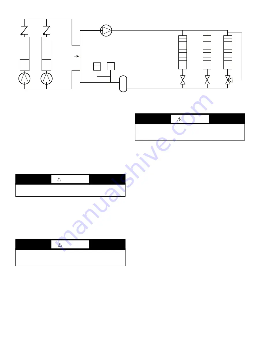
Carrier 09FC020 Скачать руководство пользователя страница 18

18

Fig. 16 — 

Typical Air Separator and Expansion Tank Location on Primary-Secondary Systems

FIELD PIPING
When facing the coil header side of the unit, the inlet (return)

water connection is on the right. It is required that a field-sup

-

plied strainer with a minimum size of 20 mesh and blow-down

valve be installed within 10 ft (3.05 m) of the unit connection

to  prevent debris from  damaging coil tubes. The blow-down

valve  allows  removal  of  particulates  caught  in  the  strainer

without  complete  removal of  the  screen. The outlet  (supply)

water connection is on the left.

The  09FC  has  water-side  Victaulic-type  connections.  Provide

proper support for the piping. If security grilles have been added,

holes must be cut in the grilles for field piping and insulation, if

required.

Victaulic Coupling Installation

1. The outside surface of the pipe, between the groove and the

pipe end, must be smooth and free from indentations, projec

-

tions (including weld seams), and roll marks to ensure a leak-

tight  seal.  All  oil,  grease,  loose  paint,  and  dirt  must  be

removed.

2. Apply a thin coat of Victaulic lubricant or silicone lubricant to

the gasket sealing lips and exterior.

3. Position the gasket over the pipe end. Make sure the gasket

does not overhang the pipe end.

4. Align and bring the two pipe ends together. Slide the gasket

into position and center it between the groove in each pipe

end.  Make  sure  no  portion  of  the  gasket  extends  into  the

groove in either pipe end.

5. Install the housings over the gasket.

NOTE:  Make  sure  the  housings'  keys  engage  the  grooves

completely on both pipe ends.

6. Install the bolts, and thread a nut finger-tight onto each bolt.

For couplings supplied with stainless steel hardware, apply an

anti-seize compound to the bolt threads. Make sure the oval

neck of each bolt seats properly in the bolt hole.

7. Tighten the nuts evenly by alternating sides until metal-to-

metal contact occurs at the bolt pads. Make sure the housings'

keys engage the grooves completely.
NOTE: It is important to tighten the nuts evenly to prevent

gasket pinching.

8. Visually inspect the bolt pads at each joint to ensure metal-to-

metal contact is achieved.

See Fig. 18-22 for a typical piping diagram of a 09FC unit. Drain

connections are located at the bottom of the entering and leaving

water piping at the end of the unit. See Fig. 5-11 for connection lo

-

cation. 

The EWT and LWT thermistors are field-installed. See Fig. 17.

The thermistors are supplied with the unit coiled up near the enter

-

ing and leaving water connections. Thermowells are included with

the unit and are placed in the control panel. Thermowells are 

1

/

4

in.

NPT to be installed in entering and leaving piping. Allow 4 pipe

diameters or straight pipe upstream of thermistor mounting loca

-

tion  to achieve mix flow  for  an  accurate  temperature  measure

-

ment.  See  Fig.  18-21  for  suggested  locations.  On  larger  units,

09FC050-080, the LWT thermowell must be placed in the com

-

mon piping if unit is piped in parallel arrangement. 

In sound sensitive applications, consider the installation of piping

vibration isolators. 

NOTE: Expansion tanks for 30XV/09FC hydronic kits must be installed for chillers piped in parallel in the primary water loop.

Zone 1

Zone 2

Zone 3

Distribution Pump

Air Separator
with Vent

Expansion
Tank(s)

Decoupler

Chiller 1

Chiller 2

09FC

09FC

WARNING

Safely  relieve  the  pressure,  and  check  for  zero  residual

pressure before removing the caps.

CAUTION

Always use a compatible lubricant to prevent the gasket from

pinching or tearing during installation. Failure to follow this

instruction could result in joint leakage.

CAUTION

Make sure the gasket does not become rolled or pinched while

installing the housings. Failure to follow this instruction could

cause damage to the gasket, resulting in joint leakage.

Содержание 09FC020

Страница 1: ...ART SNOW CLEARING START UP 53 SERVICE 53 Alarms 53 NON OPERATIONAL COMPONENT ALARM REVERSE LOAD WATER FLOW ALARM THERMISTOR ALARM FAN VFD FAILURE Alarm Troubleshooting 54 LEAVING WATER TEMPERATURE ALA...

Страница 2: ...been given instruction DANGER Electrical shock can cause personal injury and death After unit power is disconnected wait at least 20 minutes for the Variable Frequency Drives VFD capacitors to discha...

Страница 3: ...itrogen Shipping Charge 5 psig Fans and Motors Shrouded Axial Type Vertical Discharge Quantity 4 6 8 10 12 14 16 Maximum Speed rpm r s 1140 19 Coils Type Round Tube Plate Fin No of Coils 4 6 8 10 12 1...

Страница 4: ...at Cu Tube Al Fin Not Used Not Used Piping Valve Options 3 way Valves Electrical Options 0 Single Point Power Fused Disconnect High SCCR Control Options BACNet Shipping Options 0 Coil Covers 1 Coil Co...

Страница 5: ...922 1069 916 1063 884 1069 932 1127 Table 3 Unit Operating Corner Weights kg UNIT SIZE OPERATING WEIGHT AT CORNER WEIGHTS LBS A B C D E F G H 020 450 516 456 523 030 639 754 643 758 040 433 501 418 4...

Страница 6: ...consists of coil protection only Skids are not provided unless selected as a shipping option If overhead rigging is not available at the jobsite the unit should be placed on a skid or pad before drag...

Страница 7: ...ove the top of the unit and coils 5 If overhead rigging is not available the unit can be moved on roller or dragged When unit is moved on roller the unit steel skid if equipped must be removed To lift...

Страница 8: ...8 Fig 5 09FC 020 Unit Dimensions...

Страница 9: ...9 Fig 6 09FC 030 Unit Dimensions...

Страница 10: ...10 Fig 7 09FC 040 Unit Dimensions...

Страница 11: ...11 Fig 8 09FC 050 Unit Dimensions...

Страница 12: ...12 Fig 9 09FC 060 Unit Dimensions...

Страница 13: ...13 Fig 10 09FC 070 Unit Dimensions...

Страница 14: ...14 Fig 11 09FC 080 Unit Dimensions...

Страница 15: ...supplied See Fig 5 11 Be sure unit is level to within 1 8 in 3 2 mm per foot for factory sup plied drains to operate properly NOTE For units that are point loaded such as those using rubber and shear...

Страница 16: ...DE OF UNIT BASE RAIL OUTER SIDE OF UNIT BASE RAIL 0 1 3 4 44 mm 1 50 DIA 38 mm RIGGING HOLE B B 0 5 127 mm 0 875 DIA 22 mm MOUNTING HOLE MOUNTING PLATE 0 3 15 16 100 mm 0 1 9 16 39 89 mm REF 0 7 7 8 2...

Страница 17: ...tems equipment should be provided to eliminate all air from the system The amount of air that water can hold in solution depends on the pressure and temperature of the water air mixture Air is less so...

Страница 18: ...properly in the bolt hole 7 Tighten the nuts evenly by alternating sides until metal to metal contact occurs at the bolt pads Make sure the housings keys engage the grooves completely NOTE It is impor...

Страница 19: ...e reattached add the joining pipe include in the Modular Piping Accessory Part No 09FC70000801 Attach with the existing couplings Add insula tion back to the tees and joining pipe section Fig 18 09FC...

Страница 20: ...nimum access is a recommendation Local code may require increased spacing 3 Chiller tube service must be done from control panel end for this arrangement See chiller certified drawings for details 09F...

Страница 21: ...ote 2 09FC Control Panel NOTES 1 Allow 36 in for fan VFD access Verify 36 in meets local codes 2 EWT and LWT thermistors must be installed in the field Thermistors are supplied inside control panel Ad...

Страница 22: ...y protection NOTE Do not use automobile antifreeze or any other fluid that is not approved for heat exchanger duty Only use appropriately in hibited glycols concentrated to provide adequate protection...

Страница 23: ...Rt equals the equivalent pressure drop which R1 and R2 are the individual circuits Curves are for 30 Propylene Glycol PG Use multipliers for other fluids or brine concentration amounts Fig 25 09FC 02...

Страница 24: ...FC Mode Bypass Mode GPM ft wc WARNING Electrical shock can cause personal injury and death Shut off all power to this equipment during installation There may be more than one disconnect switch Tag al...

Страница 25: ...414 506 4 8 39 6 40 40 575 518 633 3 8 31 4 35 35 380 50 342 418 5 9 48 8 50 50 400 360 440 5 6 46 4 50 50 415 374 456 5 4 44 7 50 50 440 396 480 5 1 42 2 45 45 050 380 60 342 418 10 5 8 59 5 60 60 40...

Страница 26: ...ng Manangement System CB Circuit Breaker EWT Entering Water Temperature FU Fuse FM Fan Motor GND Ground IN Thermistor or Dry Contact Input LWT Leaving Water Temperature OAT Outdoor Air Temperature R1...

Страница 27: ...ocation of field power entry Be sure to seal entering power wire conduit per NEC requirements 3 Maximum field wire sizes allowed by lugs on fused discon nect are listed in Table 4 4 Terminals for fiel...

Страница 28: ...NICATION OPTIONS The 09FC controls can support communication via BACnet ARC156 156 kbps or BACnet MS TP 9600 bps 76 8 kbps Wiring for BACnet communication is at Net Net and Shield at the top left of t...

Страница 29: ...upper corner post bolts and slide the baffle un derneath the flange bolt Tighten the bolt Drill holes in the bottom of the flange of the baffle and mount with two screws to secure the bottom to the c...

Страница 30: ...er The Carrier AppController is the heart of the control system It contains the operating software and controls the operation of the machine The CarrierAppController software continuously evalu ates i...

Страница 31: ...uld be set to the upper position for thermistor IN 5 jumper should be on Fig 33 Carrier AppController Jumper Settings Carrier Equipment Touch Display Equipment touch is the user interface for the Carr...

Страница 32: ...evel None Home Click on the right to navigate to Snapshot screen The HOME screen is the main screen Displays Leaving water temperature Outdoor air temperature Operating Mode Run Command Occupancy Pass...

Страница 33: ...ic password level are visible Password Level None Properties Status This menu shows the status or value of the listed point Password Level None Properties Unit Configuration Cooling Lockout Default 50...

Страница 34: ...0 F hi 245 Range 100 to 245 F Non Operational Comp This drives the Non Operational Component alarm The is the alarm offset value CWST This is a low limit alarm offset Reverse Load Water Flow This alar...

Страница 35: ...lect the exclamation point in the top left of the screen from the Snapshot screen Trends NOTE Example screen shown Review trends for points that have trending enabled Access from the Snapshot screen b...

Страница 36: ...36 Table 8 App Controller Screen Navigation cont SCREEN NAMES DISPLAY Properties Alarms Alarm Help 11 screens Password Level None...

Страница 37: ...ller Screen Navigation cont SCREEN NAMES DISPLAY DETAILS Properties Alarms Alarm History Password Level None Properties Startup Wizard Password Level Factory Properties Startup Wizard Fan Speed PID Pa...

Страница 38: ...38 Properties Startup Wizard Mixing Valve PID Password Level Factory Table 8 App Controller Screen Navigation cont SCREEN NAMES DISPLAY DETAILS...

Страница 39: ...39 Table 8 App Controller Screen Navigation cont SCREEN NAMES DISPLAY Properties Startup Wizard Help 11 screens Password Level Factory...

Страница 40: ...ion cont SCREEN NAMES DISPLAY DETAILS Properties ET System Password Level Factory Properties ET System Module Status Password Level Factory Properties ET System Alarms Password Level Factory Propertie...

Страница 41: ...ctory Properties ET System Setup Module Setup Communication Password Level Factory Properties ET System Browser Password Level Factory Properties Touchscreen Setup Password Level Admin Table 8 App Con...

Страница 42: ...60 VFD 1 400 50 VFD 1 400 60 VFD 1 415 50 VFD 1 460 60 VFD 1 575 60 VFD 1 050 380 50 VFD 1 VFD 2 380 60 VFD 1 VFD 2 400 50 VFD 1 VFD 2 400 60 VFD 1 VFD 2 415 50 VFD 1 VFD 2 460 60 VFD 1 VFD 2 575 60 V...

Страница 43: ...Display Line 1 1 Small 0 21 Display Line 1 2 Small 0 22 Dis play Line 1 3 Small 0 23 Display Line 2 Large and 0 24 Dis play Line 3 Large The settings are accessed by selecting QUICK MENU Q3 Function...

Страница 44: ...u key is used for programming all parameters These can be accessed immediately unless a password has been created via 0 60 Main Menu Password 0 61 Access to Main Menu without Password 0 65 Personal Me...

Страница 45: ...0 0 3 02 Min Reference Hz 0 0 0 0 0 0 0 0 0 0 0 3 03 Max Reference Hz 60 60 60 60 60 60 60 60 60 60 60 3 13 Type Reference remote 1 1 1 1 1 0 0 0 0 0 0 3 15 Src Ref 1 analog input 1 1 1 1 1 1 1 1 1 1...

Страница 46: ...pendent 30 4 45 6 60 8 45 6 30 4 45 6 45 6 53 2 53 2 60 8 60 8 Voltage 460V 60 of V s 2V 3V 4V 5V 6V 7V 8V Drive Designation FVFD 1 FVFD 1 FVFD 1 FVFD 1 FVFD 2 FVFD 1 FVFD 2 FVFD 1 FVFD 2 FVFD 1 FVFD...

Страница 47: ...C link voltage drops below the undervoltage limit the frequency converter checks if a 24 V DC back up supply is connected If no 24 V DC back up supply is connected the frequency converter trips after...

Страница 48: ...ient temperature too high Motor cables too long Incorrect airflow clearance above and below the frequency converter Blocked airflow around the frequency converter Damaged heat sink fan Dirty heat sink...

Страница 49: ...the power card is either too hot or too cold Check that the ambient operating temperature is within limits Check for clogged filters Check fan operation Check the power card 072 Alarm Emergency Stop A...

Страница 50: ...10V Fan Initial Start Speed The speed that the module s fans are briefly run on initial startup D 100 R 0 to 100 Fan Minimum Speed The lowest speed that the module s fan is commanded when the fans va...

Страница 51: ...ly Setpoint BAV chws_setpoint 3024 R W 15 75 F 44 Cooling Lockout Offset BAV oat_cl_lockout_offset 3027 R W 1 10 F 3 Cooling Lockout Temperature BAV oat_cl_lockout 9002 R W 20 80 F 50 Power Fail Resta...

Страница 52: ...er allows the controller to transmit more messages while it has the token but it also increases the overall time it takes for the token to pass through the network For a router set this value to a hig...

Страница 53: ...N OPERATIONAL COMPONENT ALARM If LWT Cooling Lockout Temp Cooling Lockout Offset Non Operational Component Alarm Offset and Unit is in free cooling mode for 3 minutes alarm contact will close valves w...

Страница 54: ...a Sensor reading at controller is out of range Action Taken by Controller Alarm shown on display and alarm output energized Reset Method Automatic once reading is back in range Possible Causes Loose c...

Страница 55: ...n controller health See table below Error Lights based on controller health See table below If Run LED shows And Error LED shows Status is 1 flash per second 1 flash per second alternating with the Ru...

Страница 56: ...a handle inserted into the actuator See Fig 41 Fig 41 Manual Valve Operation Valve Linkage Adjustment This information will help return the valve linkage to the proper configuration to assure optimum...

Страница 57: ...5 and 6 Replacing Thermistors EWT LWT Add a small amount of thermal conductive grease to the thermis tor well and end of probe For all probes tighten the retaining nut 1 4 turn past finger tight See F...

Страница 58: ...046 55 13 8 628 57 14 8 232 59 15 7 857 61 16 7 500 63 17 7 152 64 18 6 841 66 19 6 536 68 20 6 247 70 21 5 972 72 22 5 710 73 23 5 461 75 24 5 225 77 25 5 000 79 26 4 786 81 27 4 582 82 28 4 389 84...

Страница 59: ...point or boiling point of water using either voltage drop measured across thermistor at the J3 terminal by determining the resistance with unit shut down and thermistor disconnected from J3 Com pare...

Страница 60: ...Avoid the use of coil brighteners acid cleaning prior to painting high pressure washers poor quality water for cleaning Totaline Indoor and Outdoor Coil Cleaner is non flammable hy poallergenic nonba...

Страница 61: ...ded Routine Periodic clean water rinse especially in coastal and indus trial applications Check heat exchanger coils for debris clean as necessary Every 3 months Check all joints and valves for leaks...

Страница 62: ...WIRING IS IN ACCORDANCE WITH NATIONAL ELECTRICAL CODE NEC U S A FIELD MODIFICATIONS OR ADDITIONS MUST BE IN COMPLIANCE WITH ALL APPLICABLE CODES 3 WIRING FOR MAIN FIELD POWER SUPPLY MUST BE RATE 75 C...

Страница 63: ...reset and current active alarms are displayed D Inactive R Inactive Active Point Name Description Default Range Cool Enable Enables or disables cooling operation D Enable R Disable Enable Lvg Wtr Temp...

Страница 64: ...point is increased by this number of degrees when receiving a Demand Level 3 signal D 3 F R 0 to 10 F Point Name Description Default Range Leaving Water Temperature Alarm Low Leaving Water Temp Alarm...

Страница 65: ...emperature value over the network The remote controller must have a network accessible outdoor air temperature sensor value D 999 F R 50 to 150 F System Control Setpoint Allows using another controlle...

Страница 66: ...hysical sensor is wired and connected to the appropriate input channel of this controller Network A network sensor value provided to this controller Locked Value The controller s sensor input is manua...

Страница 67: ...Num I O Type Sensor Actuator Type Min Max or Resolution I O configuration parameter for the points listed below Changing these parameters could cause improper control and or equip ment damage Use ext...

Страница 68: ...ed The lowest speed that the module s fan is commanded when the fans variable frequency drive is enabled D 20 R 0 to 100 Fan Speed PID This BACnet Object calculates the amount of fan speed required to...

Страница 69: ......

Страница 70: ...es the right to discontinue or change at any time specifications or designs without notice and without incurring obligations Catalog No 04 53090030 01 Printed in U S A Form 09FC 1SI Pg 70 3 21 Replace...

Страница 71: ...es No 4 Electrical power wiring is installed properly Yes No 5 Unit is properly grounded Yes No 6 Electrical circuit protection has been sized and installed properly Yes No 7 All terminals are tight Y...

Страница 72: ...than 2 Contact local utility for assistance 2 Verify flow rate Set unit in free cooling mode prior to setting flow rate Pressure entering unit _____ psig kPa Pressure leaving unit _____ psig kPa Unit...

Отзывы: