


62-11785
7–22
00061
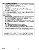
DOOR OPEN (DS1)
• ACTIVATION: DS1 is set to trigger an alarm if the switch is activated (opened or closed, depending on
switch type) for more than five seconds.
• UNIT CONTROL: May be configured as alarm only or alarm and shutdown.
• RESET CONDITION:
Alarm Only: Auto reset after the switch has de-activated for more than five seconds.
Shutdown: Auto reset after three minutes (minimum off time for door open condition) and the switch
has de-activated for more than five seconds.
NOTE: Follow the steps below until a problem is found. Once a repair or correction has been made, the active
alarm should clear itself (refer to reset condition above). Operate the unit through the appropriate modes to see
if any active alarm occurs. Continue with the steps below as necessary.
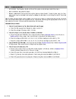
CORRECTIVE ACTIONS:
IF A SWITCH IS INSTALLED
1.
Determine What DS1 is Activated By
- DS1 may be connected to a compartment door or some other
device. Locate the device used as DS1.
2.
Check To See If DS1 has Activated
- Inspect device used to activate DS1. For example, compartment
door must be closed, and switch must be de-activated.
3.
Check Configuration for DS1
- Verify that Configuration is set for the type of switch being used (i.e.
when switch is activated, switch contacts are closed; etc). Configuration must agree with switch type.
Refer to
.
4.
Check Wiring
a. Visually inspect wiring to DS1 to make sure it is connected.
b. Visually inspect condition of switch. It must not be damaged, wet, corroded, etc.
c. Check circuit. (See wiring schematic
.) With the switch contacts closed, check for
minimum 11 VDC from 2SVM-13, through the wiring and switch back to 2SVM-24.
5.
Temporary Solution Tip
- In the event of a defective switch that can not be repaired or replaced, and the
switch is forcing the unit into a shutdown or low speed, this action may be temporarily overridden by set-
ting the correct Functional Parameter. Set the Override Door Switch Shutdown Functional Parameter to
YES.
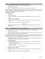
IF A SWITCH IS NOT INSTALLED
1.
Check Configurations
- Any switch/sensor not present in the unit should not be Configured “ON”. Cor-
rect Configurations.
2.
Check Connector
- Locate and inspect the DS or REM 10 position connector for optional sensors and
switches (see wiring schematic
). Connector must have cap on. No corrosion or moisture
inside connector.
If there is a problem with the DS connector and no switch is installed, the connector may be removed
and both wires separated, terminated and insulated with heat shrink.
If there is no DS connector, there is a problem with the REM connector and there are no remote sen-
sors or switches in the unit, the connector may be removed and each individual wire separated from
the others, terminated and insulated with heat shrink.
Содержание VECTOR 8100
Страница 2: ......
Страница 4: ......
Страница 12: ...62 11785 viii ...
Страница 16: ...62 11640 12 ...
Страница 18: ...62 11785 ...
Страница 24: ...62 11785 1 6 1 3 SAFETY DECALS ...
Страница 25: ...1 7 62 11785 ...
Страница 26: ...62 11785 1 8 ...
Страница 27: ...1 9 62 11785 ...
Страница 28: ...62 11785 1 10 ...
Страница 30: ...62 11785 ...
Страница 50: ...62 11785 ...
Страница 82: ...62 11785 ...
Страница 96: ...62 11785 4 14 ...
Страница 98: ...62 11785 ...
Страница 129: ...5 31 62 11785 ...
Страница 130: ...62 11785 5 32 ...
Страница 134: ...62 11785 6 4 ...
Страница 138: ...62 11785 ...
Страница 230: ...62 11785 ...
Страница 271: ...8 41 62 11785 ...
Страница 272: ...62 11785 8 42 ...
Страница 274: ...62 11785 ...
Страница 286: ......
Страница 287: ......
Страница 288: ...62 11785 10 8 ...
Страница 292: ......
Страница 293: ......