


62-11785
7–2
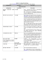
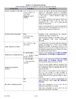
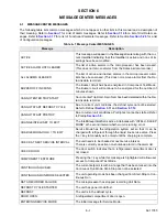
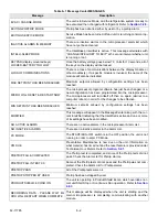
7.2
NOTES
NOTE
Note 1:
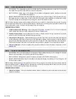
The active alarm list may be cleared when in the Driver Mode or Advanced User Mode by
pressing the CLEAR ALARMS soft key. That is: the alarm is “cleared” from the active alarm list and
moved to the inactive alarm list for later review if the condition that caused the alarm has been cor-
rected. When Shutdown Alarms are cleared, the unit will attempt to restart. When non-Shutdown
Alarms are cleared, there will be no noticeable change in the unit’s operation.
The Inactive Alarm list may be cleared when in the Technician Mode in the same way. From the inac-
tive alarm list the technician has the option to “Clear Inactive” alarms only or to “Clear All” alarms.
Clearing the inactive alarm list removes the alarm from the system. However alarms that have been
activated will remain in the data recorder.
NOTE
Note 2:
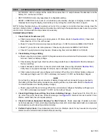
The Virtual Tech system may provide a “signal” voltage when a circuit is not energized (nomi-
nal 3 to 5 volts). This signal voltage is used by the APX Control System to activate an alarm message
if there is a problem in the circuit but should not be used for component testing.
When instructed to test for voltage, energize the component using Component Test Mode to ensure
the correct voltage is being read. Refer to
. Also, testing may be performed without the
unit starting. To do this, place the unit in PC Mode before using Component Test Mode. Refer to
.
NOTE
Note 3:
Sensors may be tested by taking a resistance measurement, at the sensor side of the harness
connector, at the sensor location. To do this, being careful not to damage the connector pins, discon-
nect the sensor from the harness and measure resistance. Refer to
for chart of resistances
for different sensors.
The interconnecting wiring may also be tested by checking for continuity between the harness side of
the connector at the sensor location and the harness side of the connector at the module.
NOTE
Note 4:
The switches, (door/remote, high pressure, and defrost air) may be tested by checking conti-
nuity, at the switch side of the harness connector, at the switch location. To do this, being careful not to
damage the connector pins, disconnect the switch from the harness and check continuity to determine
if the switch is open or closed.
The interconnecting wiring for the door/remote and defrost air switches may also be tested by check-
ing for continuity between the harness side of the connector at the switch location and the harness
side of the connector at the module.
The high pressure switch (HPS) interconnecting wiring may be tested by checking for continuity
between the harness side of the connector at the high pressure switch location and the PCM or J-1
harness connector.
NOTE
Note 5:
Some tests can only be conducted while the unit is operating. The unit may be started auto-
matically by placing the SROS in the Start/Run position.
Содержание VECTOR 8100
Страница 2: ......
Страница 4: ......
Страница 12: ...62 11785 viii ...
Страница 16: ...62 11640 12 ...
Страница 18: ...62 11785 ...
Страница 24: ...62 11785 1 6 1 3 SAFETY DECALS ...
Страница 25: ...1 7 62 11785 ...
Страница 26: ...62 11785 1 8 ...
Страница 27: ...1 9 62 11785 ...
Страница 28: ...62 11785 1 10 ...
Страница 30: ...62 11785 ...
Страница 50: ...62 11785 ...
Страница 82: ...62 11785 ...
Страница 96: ...62 11785 4 14 ...
Страница 98: ...62 11785 ...
Страница 129: ...5 31 62 11785 ...
Страница 130: ...62 11785 5 32 ...
Страница 134: ...62 11785 6 4 ...
Страница 138: ...62 11785 ...
Страница 230: ...62 11785 ...
Страница 271: ...8 41 62 11785 ...
Страница 272: ...62 11785 8 42 ...
Страница 274: ...62 11785 ...
Страница 286: ......
Страница 287: ......
Страница 288: ...62 11785 10 8 ...
Страница 292: ......
Страница 293: ......