


62-11785
8–20
8.7.7
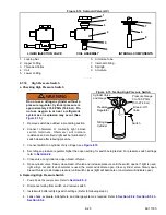
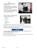
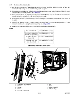
Compressor Suction Modulation Valve (CSMV)
The purpose of the CSMV (see
maintain the compressor within its operating envelope,
maximize unit capacity and maintain temperature
control.
If it is suspected that the CSMV is malfunctioning, the
most efficient method of diagnosing the valve is to run
a Pretrip (refer to
). The Pretrip steps will
check the remainder of the system and the CSMV
specific test will check the valve. During the CSMV
specific test the valve will be brought to a preset
position, the unit started and then the valve will be
opened while the control system monitors suction
pressure.
If there is a problem with the valve internal motor/piston
assembly or control system wiring to the valve the test
will fail.
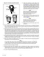
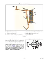
Figure 8.10 Suction Modulation Valve (CSMV)
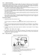
a. Diagnostics - Control System or Wiring
NOTE
The APX Micro Service Harness, Carrier P/N 07-00515-00 can be used for this procedure.
1. Disconnect the CSMV connector.
2. Place the START/RUN-OFF switch in the START/RUN position, DO NOT ALLOW THE UNIT TO START. When
the MessageCenter displays “SMV CLOSING”, measure the AC voltage on the harness side of the connector
between pins A & B and then between C & D. A voltage (10 to 16 VAC) should be read by the digital voltmeter for
each pair of wires. If the reading is present on all of the wire pairs there is a good signal coming from the control
system.
3. If the reading is not present on one or more of the wire pairs, check the wiring between the control system and
the CSMV connector, or check the control system for proper model number Configuration.
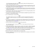
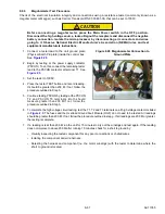
b. Diagnostics - Stepper Motor (SMV)
The valve stepper motor may be tested using a stepper motor drive tester or ohmmeter.
1. To test with a stepper motor drive tester (Carrier Transicold P/N 07-00375-00SV), connect the 4 pin test cable
supplied with the tester to the valve connector, refer to
, and the cable wires to the tester in
accordance with wire and terminal color.
2. Set the step rate to 150 steps per second and either open or close the valve. Each red LED should light
sequentially until all four are illuminated. Any LED failing to illuminate indicates an open on that leg, and a need
to replace the piston and drive motor assembly.
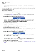
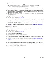
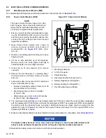
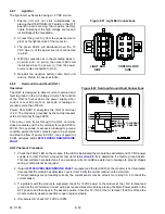
3. To test with an ohmmeter, check the winding
resistance between connector pin A & B and then
between C & D, see
. In normal
ambient, the resistance between the pins should
be 65 to 84 ohms. Also check each terminal to the
coil casing (ground). If an out of tolerance or zero
reading is observed, the piston and drive motor
assembly is to be replaced.
Figure 8.11 CSMV Coil
4 Pin Connector
Drive & Motor
Assembly
Screws
Body
1
2
A (BLACK)
(WHITE) B
(RED) C
D (GREEN)
Содержание VECTOR 8100
Страница 2: ......
Страница 4: ......
Страница 12: ...62 11785 viii ...
Страница 16: ...62 11640 12 ...
Страница 18: ...62 11785 ...
Страница 24: ...62 11785 1 6 1 3 SAFETY DECALS ...
Страница 25: ...1 7 62 11785 ...
Страница 26: ...62 11785 1 8 ...
Страница 27: ...1 9 62 11785 ...
Страница 28: ...62 11785 1 10 ...
Страница 30: ...62 11785 ...
Страница 50: ...62 11785 ...
Страница 82: ...62 11785 ...
Страница 96: ...62 11785 4 14 ...
Страница 98: ...62 11785 ...
Страница 129: ...5 31 62 11785 ...
Страница 130: ...62 11785 5 32 ...
Страница 134: ...62 11785 6 4 ...
Страница 138: ...62 11785 ...
Страница 230: ...62 11785 ...
Страница 271: ...8 41 62 11785 ...
Страница 272: ...62 11785 8 42 ...
Страница 274: ...62 11785 ...
Страница 286: ......
Страница 287: ......
Страница 288: ...62 11785 10 8 ...
Страница 292: ......
Страница 293: ......