


8–29
62-11785
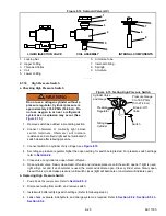
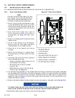
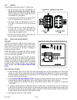
8.8.3
Stepper Valve Module (SVM)
1. Ensure unit will not start automatically by placing the START/RUN-OFF switch in the OFF position and
removing the negative battery cable. Disconnect the high voltage source and lockout/tagout the receptacle.
2. Unlock tabs on and remove the two 35 pin connectors and 8 pin connector from the front of the module.
3. Replace module. Tighten mounting hardware to 96 inch/lbs (10.8 Nm).
4. Reinstall connectors ensuring tabs are fully locked in place.
5. Reinstall the negative battery cable, start unit and run Pretrip to check operation.
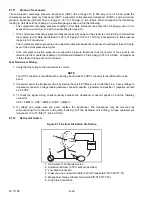
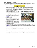
8.8.4
Display Module (DM)
1. Ensure unit will not start automatically by placing the START/RUN-OFF switch in the OFF position and
removing the negative battery cable. Disconnect the high voltage source and lockout/tagout the receptacle.
2. Unlock the tabs on, and then remove the 14 pin connector from the back of the module.
3. Remove hardware at rear of module. Replace module. Tighten mounting hardware to 84 to 120 inch/lbs (9.5 to
13.6 Nm).
4. Reinstall connector ensuring tabs are fully locked in place.
5. Reinstall the negative battery cable.
6. Make sure the latest software has been loaded to ensure all modules are compatible, refer to
NOTICE
When a module is replaced, software should be upgraded before switching the unit on. This
will ensure software compatibility of all modules.
7. Start unit and run Pretrip to check operation.
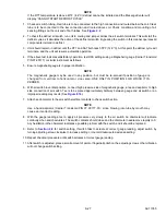
8.8.5
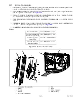
Contactor Control Board (CCB)
1. Ensure the unit will not start automatically by placing the START/RUN-OFF switch in the OFF position and
removing the negative battery cable. Disconnect the high voltage source and lockout/tagout the receptacle.
NOTICE
Electronic modules MUST be handled with care to prevent accidental damage or degradation
from electrical static discharge (ESD), contamination or abuse. Before touching a module,
touch your body and/or conductive tool being used to the frame to discharge ESD safely. All
electronics should be handled carefully and only held by edges of any exposed board. Care
should be taken when inserting/extracting connectors and components to avoid exerting
excessive stress on the board which could fracture small components nearby, resulting in
future failure of circuit.
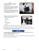
2. Attach a grounded wrist strap (CTD P/N 07-00304-00) and ground it to a good unit frame ground.
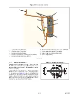
3. Remove the four control box cover bolts, then the remove the cover ground cable. Set the cover off to the side.
4. Remove the 2 nuts that secure the (Physical Earth) PE plate to the box and remove the 2 nuts that secure the
current transformer to the control box.
5. Move the PE plate and the current transformer off the studs towards the center of the box.
6. Remove the two nuts located at the bottom of the sub panel.
7. Disconnect the connectors from CCB1 and CCB2 and remove two nuts.
8. Remove upper mounting bolts.
Содержание VECTOR 8100
Страница 2: ......
Страница 4: ......
Страница 12: ...62 11785 viii ...
Страница 16: ...62 11640 12 ...
Страница 18: ...62 11785 ...
Страница 24: ...62 11785 1 6 1 3 SAFETY DECALS ...
Страница 25: ...1 7 62 11785 ...
Страница 26: ...62 11785 1 8 ...
Страница 27: ...1 9 62 11785 ...
Страница 28: ...62 11785 1 10 ...
Страница 30: ...62 11785 ...
Страница 50: ...62 11785 ...
Страница 82: ...62 11785 ...
Страница 96: ...62 11785 4 14 ...
Страница 98: ...62 11785 ...
Страница 129: ...5 31 62 11785 ...
Страница 130: ...62 11785 5 32 ...
Страница 134: ...62 11785 6 4 ...
Страница 138: ...62 11785 ...
Страница 230: ...62 11785 ...
Страница 271: ...8 41 62 11785 ...
Страница 272: ...62 11785 8 42 ...
Страница 274: ...62 11785 ...
Страница 286: ......
Страница 287: ......
Страница 288: ...62 11785 10 8 ...
Страница 292: ......
Страница 293: ......