


5–1
62-11785
SECTION 5
CONTROL SYSTEM INTERFACE
5.1
INTERFACE METHODS
There are four methods for interfacing with the APX Control System:
1. Driver/Advanced User Interface - Driver & Advanced User Interface activities such as start, stop, Pretrip,
reading alarms, reading data and changing Functional Parameters may all be performed using the display
mounted keys (refer to
).
2. Technician Mode - code based access. Technician Mode includes: technician hour meters, inactive alarms,
configuration settings, Component Test Mode and Service Mode.
3. USB memory device - Activities using the USB memory device include, creation of the device, PC Mode,
downloading data files, installing software, and transferring configuration files.
4. TRU-Tech/TRU-View - Access using a computer and service cable.
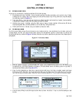
5.2
TECHNICIAN MODE
The Technician Mode allows the technician to view inactive alarms, view additional hour meters, work with
Configurations, test the unit components and/or service the refrigeration system. Instructions for entering the
Technician Mode are provided in
while information on these operations is provided in the following sub-
paragraphs.
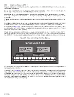
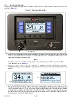
Figure 5.1 Technician Mode
1. With the system powered up (START/RUN-OFF switch in the START/RUN position) or in PC Mode press
the MENU key until TECH MODE is displayed. If TECH MODE does not display, place the system in
Advanced User Mode (refer to
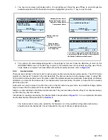
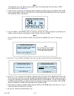
2. Press the TECH MODE key. Enter the master technician PIN code. The factory installed master technician
PIN code is 7435. Enter the code by pressing the 3&4 keys simultaneously, then press the 4 key, the 3 key,
then the 1&4 keys simultaneously. Once the code is entered, press the “=” key to enter Technicians Menu.
3. Press the
▲
or
▼
key to scroll through the list of menu items. Press the “=” key to enter the settings or test
modes.
START/STOP
ELECTRIC
COOL
Viewing Menu Soft Key
TECH
Selections
Press Menu Key to Scroll
MODE
START/STOP
ELECTRIC
COOL
BOX TEMPERATURE
o
F
SETPOINT
o
F
STATUS OK
34
.3 34
Enter Code
__________________
TECHNICIANS MENU (1 OF 4)
CONFIGURATION SETTINGS
BACK
EXIT
COMPONENT TEST MODE
SERVICE MODE
CANCEL TECHNICIAN MODE/PIN ACCESS
END OF LIST
Содержание VECTOR 8100
Страница 2: ......
Страница 4: ......
Страница 12: ...62 11785 viii ...
Страница 16: ...62 11640 12 ...
Страница 18: ...62 11785 ...
Страница 24: ...62 11785 1 6 1 3 SAFETY DECALS ...
Страница 25: ...1 7 62 11785 ...
Страница 26: ...62 11785 1 8 ...
Страница 27: ...1 9 62 11785 ...
Страница 28: ...62 11785 1 10 ...
Страница 30: ...62 11785 ...
Страница 50: ...62 11785 ...
Страница 82: ...62 11785 ...
Страница 96: ...62 11785 4 14 ...
Страница 98: ...62 11785 ...
Страница 129: ...5 31 62 11785 ...
Страница 130: ...62 11785 5 32 ...
Страница 134: ...62 11785 6 4 ...
Страница 138: ...62 11785 ...
Страница 230: ...62 11785 ...
Страница 271: ...8 41 62 11785 ...
Страница 272: ...62 11785 8 42 ...
Страница 274: ...62 11785 ...
Страница 286: ......
Страница 287: ......
Страница 288: ...62 11785 10 8 ...
Страница 292: ......
Страница 293: ......