


T-372
4–52
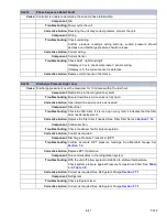
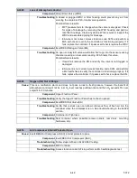
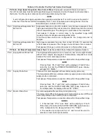
AL996
Scrubber Rotation Fault
Cause:
Feedback from the Scrubber Motor to the controller is not sensed when the motor is turning.
Component
Scrubber Fuse
Troubleshooting
Check to see if Scrubber Fuse is blown. Replace Fuse if necessary.
Component
Scrubber Motor
Troubleshooting
Run Test Mode and verify scrubber bed is turning. If back panel cannot be
removed to check, verify the scrubber amperage consumption, read at XS
contactor wire XSL1. If between 40 and 200mA, motor is rotating properly.
If no current detected, check and replace FX3. If current spiking to 350mA
for 2 seconds then dropping to 90mA, the scrubber motor is located. If
scrubber motor is locked, further inspection of the scrubber bed is
required. Unit will control CO
2
with the fresh air solenoid when this alarm
occurs if scrubber inaccessible.
If Scrubber Motor not operating, follow the troubleshooting flowchart in
XtendFresh manual and take appropriate action.
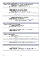
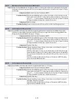
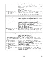
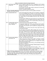
ERR#
Internal Microprocessor Failure
Cause:
The controller performs self-check routines. If an internal failure occurs, an “ERR” alarm will appear
on the display. This is an indication the controller needs to be replaced.
Error Description
ERR 0-RAM failure Indicates that the controller working memory has failed.
ERR 1-Program Memory
Failure
Indicates a problem with the controller program.
ERR 2-Watchdog time-
out
The controller program has entered a mode whereby the controller
program has stopped executing.
ERR 3-N/A N/A
ERR 4-N/A N/A
ERR 5-A-D failure The controller’s Analog to Digital (A-D) converter has failed.
ERR 6-IO Board failure Internal program/update failure.
ERR 7-Controller failure Internal version/firmware incompatible.
ERR 8-DataCORDER
failure
Internal DataCORDER memory failure.
ERR 9-Controller failure Internal controller memory failure.
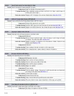
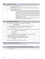
Entr StPt
Enter Set point (Press Arrow & Enter)
Cause:
The controller is prompting the operator to enter a setpoint.
LO
Low Main Voltage (Function Codes Cd27-38 disabled and No alarm stored.)
Cause:
This message will be alternately displayed with the setpoint whenever the supply voltage is less than
75% of its proper value.
Содержание PrimeLINE 69NT40-571-001
Страница 2: ......
Страница 4: ......
Страница 14: ......
Страница 36: ......
Страница 110: ......
Страница 116: ......
Страница 171: ...8 1 T 372 SECTION 8 ELECTRICAL WIRING SCHEMATIC AND DIAGRAMS Figure 8 1 Legend Standard Unit Configuration ...
Страница 172: ...T 372 8 2 ELECTRICAL WIRING SCHEMATIC AND DIAGRAMS Figure 8 2 Schematic Diagram Based on Drawing 62 11957 ...
Страница 176: ......
Страница 178: ......
Страница 180: ......
Страница 184: ......
Страница 185: ......