


T-372
7–24
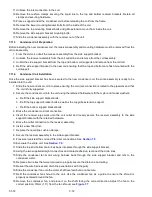
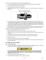
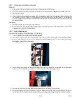
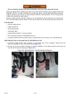
9. Remove the cap and insert the humidity sensor into the bottle through the bottle opening and pull the connector
back through the drilled hole in the cap. Then, secure the cap and seal the wire going through the cap.
NOTE
Make sure that the sensor is not at all in contact with the salt water.
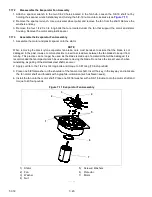
Figure 7.14 Humidity Sensor
1) Cap opening (6 cm)
2) Cap hole (3 cm)
3) Humidity Sensor (HS)
4) Salt water solution
- - - - -
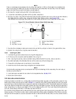
10. Allow the saturated salt mixture to settle for approximately ten minutes.
11. Reconnect the humidity sensor to the harness and power the reefer unit on.
12. Press the CODE SELECT key on the keypad.
13. Use the Arrow keys until “Cd17” is displayed then press the ENTER key.
14. This displays the humidity sensor reading. Verify the reading is between 60% and 85% relative humidity.
15. If the humidity sensor display is outside of this range, reconfirm the salt mixture and retest. If not in range,
replace the sensor at the next opportunity.
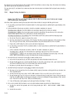
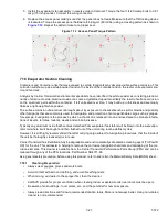
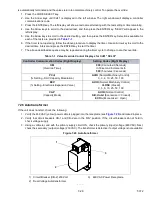
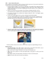
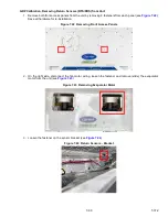
16. Wipe clean and reinstall the humidity sensor and access panel. Torque the access panel hardware to 69 kg-
cm (60 in.-lbs.) using a crossing pattern similar to the numbering below.
Figure 7.15 Access Panel Torque Sequence
17. If the panel gasket is damaged, replace it.
1
2
4
3
COOL
HEAT
DEFROST
IN RANGE
ALARM
SUPPLY RETURN
SETPOINT/Code
AIR TEMPERATURE/Data
Содержание PrimeLINE 69NT40-571-001
Страница 2: ......
Страница 4: ......
Страница 14: ......
Страница 36: ......
Страница 110: ......
Страница 116: ......
Страница 171: ...8 1 T 372 SECTION 8 ELECTRICAL WIRING SCHEMATIC AND DIAGRAMS Figure 8 1 Legend Standard Unit Configuration ...
Страница 172: ...T 372 8 2 ELECTRICAL WIRING SCHEMATIC AND DIAGRAMS Figure 8 2 Schematic Diagram Based on Drawing 62 11957 ...
Страница 176: ......
Страница 178: ......
Страница 180: ......
Страница 184: ......
Страница 185: ......