


4–41
T-372
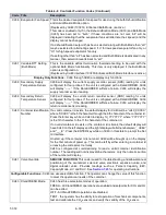
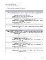
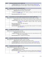
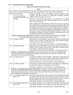
AL214
Phase Sequence Detect Fault
Cause:
Controller is unable to determine the correct phase relationship.
Component
N/A
Troubleshooting
Power cycle the unit.
Corrective Action
Resetting the unit may correct problem, monitor the unit.
Component
Wiring
Troubleshooting
Check unit wiring.
Confirm pressure readings during start-up; suction pressure should
decrease and discharge pressure should increase.
Corrective Action
Correct wiring.
Component
Current Sensor
Troubleshooting
Check Cd41, right most digit:
If display is 3 or 4, check compressor / sensor wiring.
If display is 5, the current sensor is defective.
Corrective Action
Replace current sensor if defective.
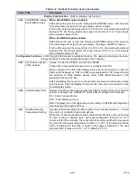
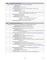
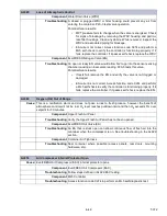
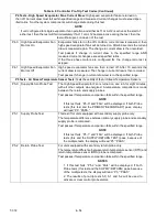
AL218
Discharge Pressure High / Low
Cause:
Discharge pressure is over the maximum for 10 minutes within the last hour.
Component
Restrictions in the refrigeration system.
Troubleshooting
Ensure liquid line service valve is fully open.
Corrective Action
Open liquid line service valve as needed.
Component
Filter Drier
Troubleshooting
Check the filter drier. If it is iced up or very cold, it indicates that the filter
drier needs replacement.
Corrective Action
Replace the filter drier if needed. See Filter Drier Service
.
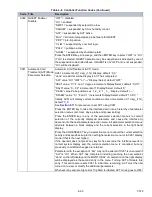
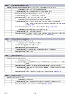
Component
Condenser Fan
Troubleshooting
Check condenser fan for proper operation.
Corrective Action
Correct as required.
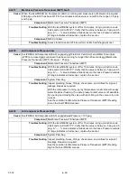
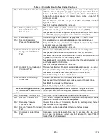
Component
Discharge Pressure Transducer (DPT)
Troubleshooting
Confirm accurate DPT pressure readings. See Manifold Gauge Set
Corrective Action
Replace DPT if defective.
Component
Non-condensables in the refrigeration system.
Troubleshooting
With the unit off, allow system to stabilize to ambient temperature.
Check system pressure against Pressure Temperature Chart. See
.
Corrective Action
Correct as required. See Refrigerant Charge
.
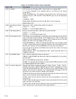
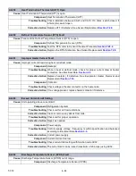
Component
Refrigerant
Troubleshooting
Check refrigerant level.
Corrective Action
Correct as required. See Refrigerant Charge
.
Содержание PrimeLINE 69NT40-571-001
Страница 2: ......
Страница 4: ......
Страница 14: ......
Страница 36: ......
Страница 110: ......
Страница 116: ......
Страница 171: ...8 1 T 372 SECTION 8 ELECTRICAL WIRING SCHEMATIC AND DIAGRAMS Figure 8 1 Legend Standard Unit Configuration ...
Страница 172: ...T 372 8 2 ELECTRICAL WIRING SCHEMATIC AND DIAGRAMS Figure 8 2 Schematic Diagram Based on Drawing 62 11957 ...
Страница 176: ......
Страница 178: ......
Страница 180: ......
Страница 184: ......
Страница 185: ......