Carrier TRANSICOLD PrimeLINE 69NT40-571-001 Скачать руководство пользователя страница 130

T-372

7–14

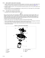
10. To make sure that the motor is aligned properly, slide the condenser fan onto the motor shaft reversed but

do not secure.

11. Rotate the fan to make sure the fan blades do not contact the shroud:

• If the fan motor is misaligned vertically, add or remove shims to align.
• If the fan motor is not properly centered, loosen the mounting bolts, and adjust the motor position on the

bracket, and then secure the motor.

12. Remove the condenser fan, and connect the fan motor wiring to the fan motor.
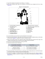
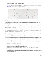
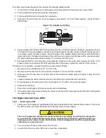
13. Place the  condenser  fan on  the shaft  facing the  correct  direction. Adjust  the fan to  the correct  position,

37mm (1.5”) from the fan shroud, see 

Figure 7.7

.

14. Use Loctite “H” on the fan set screws, and tighten.
15. Refit the left and right infill panels.
16. Refit the condenser fan grille, ensuring the grille is properly centered around condenser fan.

7.13 Water-Cooled Condenser Cleaning

The water-cooled condenser is of the shell and coil type with water circulating through the cupro-nickel coil. The

refrigerant vapor is admitted to the shell side and is condensed on the outer surface of the coil.
Rust, scale and slime on the water-cooling surfaces inside of the coil interfere with the transfer of heat, reduce sys

-

tem capacity, cause higher head pressures and increase the load on the system.
By checking the leaving water temperature and the actual condensing temperature, it can be determined if the con

-

denser coil is becoming dirty. A larger than normal difference between leaving condensing water temperature and

actual condensing temperature, coupled with a small difference in temperature of entering and leaving condensing

water, is an indication of a dirty condensing coil.
If the water-cooled condenser is dirty, it may be cleaned and de-scaled.

7.13.1

Cleaning Supplies Needed

• Oakite Aluminum Cleaner® 164, available as a powder in 20 kg (44 lb) pails and 205 kg (450 lb) drums.
• Oakite Composition No. 32, available as a liquid in cases, each containing 3.785 liters (4 U.S. gallon) bottles

and also in carboys of 52.6 kg (116 lbs) net.

• Fresh clean water.
• Acid proof pump and containers or bottles with rubber hose.

NOTE

When Oakite Compound No. 32 is used for the first time, the local Oakite technical service representative

should be called in for suggestions in planning the procedure. The representative will advise the reader on

how to do the work with a minimum dismantling of equipment: how to estimate the time and amount of

compound required; how to prepare the solution; how to control and conclude the de-scaling operation by

rinsing and neutralizing equipment before putting it back into service. The representative’s knowledge of

metals, types of scale, water conditions and de-scaling techniques will be highly useful.

7.13.2

Cleaning Procedure Summary

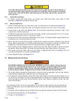
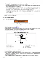
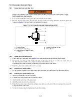
1. Turn the unit off and disconnect main power.
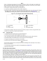
2. Disconnect the water pressure switch tubing by loosening the two flare nuts. Install a 1/4 inch flare cap on

the water-cooled condenser inlet tube (replaces tubing flare nut). De-scale tubing if necessary.

3. Drain water from the condenser tubing circuit.
4. Clean the water tubes with Oakite Aluminum Cleaner® 164 to remove mud and slime.
5. Flush.
6. De-scale the water tubes with Oakite No. 32 to remove scale.
7. Flush.
8. Neutralize.

Содержание PrimeLINE 69NT40-571-001

Страница 1: ...Container Refrigeration OPERATIONS AND SERVICE MANUAL For PrimeLINE 69NT40 571 001 to 199 PrimeLINE ONE 69NT40 575 001 to 199 Container Refrigeration Units T 372 Rev B TM ...

Страница 2: ......

Страница 3: ... 2020 Carrier Corporation Printed in USA December 2020 OPERATIONS AND SERVICE MANUAL For PrimeLINE 69NT40 571 000 to 199 PrimeLINE ONE 69NT40 575 000 to 199 Container Refrigeration Units ...

Страница 4: ......

Страница 5: ...r 2 2 2 4 7 Evaporator Fan Operation 2 2 2 4 8 Plate Set 2 2 2 5 OPTION DESCRIPTIONS 2 2 2 5 1 Battery 2 2 2 5 2 Dehumidification 2 2 2 5 3 USDA 2 2 2 5 4 Interrogator Receptacle 2 2 2 5 5 Quest 2 2 2 5 6 Autotransformer 2 3 2 5 7 Handles 2 3 2 5 8 Water Cooling 2 3 2 5 9 Back Panels 2 3 2 5 10 460 Volt Cable 2 3 2 5 11 230 Volt Cable 2 3 2 5 12 Cable Restraint 2 3 2 5 13 Upper Fresh Air Makeup 2 ...

Страница 6: ...4 4 4 3 6 Perishable Idle Mode Air Circulation 4 4 4 3 7 Perishable Heating Mode 4 4 4 3 8 Perishable Dehumidification 4 5 4 3 9 Perishable Dehumidification Bulb Mode 4 6 4 3 10 Perishable Economy Fan Mode 4 6 4 3 11 Perishable Mode Cooling Sequence of Operation 4 7 4 3 12 Perishable Mode Heating Sequence of Operation 4 8 4 3 13 Perishable Mode Trim Heat 4 8 4 3 14 Frozen Mode Temperature Control ...

Страница 7: ... Wireless Communications 4 23 4 8 CONTROLLER CONFIGURATION VARIABLES 4 25 4 9 CONTROLLER FUNCTION CODES 4 26 4 10 CONTROLLER ALARM INDICATIONS 4 37 4 11 CONTROLLER PRE TRIP TEST CODES 4 53 OPERATION 5 1 5 1 INSPECTION 5 1 5 2 CONNECT POWER 5 1 5 2 1 Connecting to 380 460 VAC Power 5 1 5 2 2 Connecting to 190 230 VAC Power 5 1 5 3 ADJUST FRESH AIR MAKEUP VENT 5 2 5 3 1 Upper Fresh Air Makeup Vent 5...

Страница 8: ...6 12 AUTOTRANSFORMER MALFUNCTION 6 4 6 13 WATER COOLED CONDENSER OR WATER PRESSURE SWITCH 6 5 6 14 COMPRESSOR OPERATING IN REVERSE 6 5 6 15 ABNORMAL TEMPERATURES 6 5 6 16 ABNORMAL CURRENTS 6 5 SERVICE 7 1 7 1 SECTION LAYOUT 7 1 7 2 MANIFOLD GAUGE SET 7 1 7 2 1 Evacuating the Manifold Gauge Set 7 2 7 3 SERVICE CONNECTIONS 7 2 7 3 1 Connecting the Manifold Gauge Set 7 3 7 3 2 Removing the Manifold G...

Страница 9: ...the Evaporator Fan Assembly 7 19 7 17 2 Disassemble the Evaporator Fan Assembly 7 20 7 17 3 Assemble the Evaporator Fan Assembly 7 20 7 18 EVAPORATOR SECTION CLEANING 7 21 7 18 1 Cleaning Preparation 7 21 7 18 2 Cleaning Procedure 7 22 7 19 ELECTRONIC EXPANSION VALVE EEV 7 22 7 19 1 Removing an EEV 7 22 7 19 2 Installing an EEV 7 22 7 20 HUMIDITY SENSOR 7 23 7 20 1 Checking the Operation of the Hu...

Страница 10: ...SOR SERVICE 7 34 7 28 1 Ice Bath Preparation 7 34 7 28 2 Sensor Checkout Procedure 7 35 7 28 3 GDP Supply and Return Sensor Calibration 7 37 7 28 4 Sensor Replacement 7 43 7 28 5 Sensor STS and SRS Reinstallation 7 45 7 28 6 Sensor RTS and RRS Reinstallation 7 45 7 28 7 Sensor DTS Reinstallation 7 46 7 28 8 Sensor ETS1 and ETS2 Reinstallation 7 46 7 28 9 Sensor CPDS Reinstallation 7 46 7 29 VENT P...

Страница 11: ...oting Sequence 4 14 Figure 4 11 DataCORDER Configuration Screen 4 20 Figure 4 12 DataCorder Probe Calibration Screen 4 21 Figure 4 13 DataCorder Probe Calibration Screen 4 21 Figure 4 14 DataCORDER Systems Tool Screen 4 22 Figure 4 15 DataLINE and DataLINE Connect 4 23 Figure 5 1 Autotransformer 5 2 Figure 5 2 Upper Fresh Air Make Up Flow Chart 5 3 Figure 5 3 TripWise Status in DataCORDER 5 9 Figu...

Страница 12: ...utting Wire Ties 7 40 Figure 7 26 DataLINE Probe Calibration 7 40 Figure 7 27 DataLINE Calibrate Sensors Button 7 41 Figure 7 28 DataLINE Enter Service Center Information 7 41 Figure 7 29 Ice Bath 7 42 Figure 7 30 DataLINE Start Cal Button 7 42 Figure 7 31 DataLINE Calibration Results 7 43 Figure 7 32 Sensor Types 7 44 Figure 7 33 Sensor and Cable Splice 7 44 Figure 7 34 Supply Sensor Positioning ...

Страница 13: ...ngs Menu nEt Options 4 24 Table 4 7 Controller Configuration Variables 4 25 Table 4 8 Controller Function Codes 4 26 Table 4 9 Controller Pre Trip Test Codes 4 53 Table 4 10 DataCORDER Pre Trip Result Records 4 59 Table 7 1 Valve Override Control Displays for Cd41 SELCt 7 29 Table 7 2 Sensor Resistance AMBS DTS ETS RRS RTS SRS STS 7 36 Table 7 3 Sensor Resistance PrimeLINE CPDS 7 37 Table 7 4 R 13...

Страница 14: ......

Страница 15: ...f and power supply is disconnected In case of severe vibration or unusual noise stop the unit and investigate 1 4 Maintenance Precautions Beware of unannounced starting of the evaporator and condenser fans Do not open the condenser fan grille or evaporator access panels before turning power off disconnecting and securing the power plug Be sure power is turned off before working on motors controlle...

Страница 16: ...ING Do not attempt to remove power plug s before turning OFF the Start Stop switch ST unit circuit breaker s and external power source WARNING Make sure the power plugs are clean and dry before connecting to power receptacle WARNING Make sure that the unit circuit breaker s CB 1 CB 2 and the Start Stop switch ST are in the O OFF position before connecting to any electrical power source WARNING Mak...

Страница 17: ...ccording to nameplate specifications to ensure optimal unit performance CAUTION Do not remove wire harnesses from controller modules unless you are grounded to the unit frame with a static safe wrist strap CAUTION Unplug all controller module wire harness connectors before performing arc welding on any part of the container CAUTION Pre trip inspection should not be performed with critical temperat...

Страница 18: ...formance and premature system failure due to the precision machinery and assembly required within the compressor To repair the unit remove the faulty compressor and replace with an approved Carrier compressor If the return of the compressor is not required follow local waste collection recycling regulations in discarding the compressor CAUTION Take necessary steps place plywood over coil or use sl...

Страница 19: ...tion 2 2 Refrigerant PrimeLINE models 69NT40 571 000 to 099 and PrimeLINE ONE models 69NT40 575 000 to 099 are units designed to only be charged with R 134a refrigerant PrimeLINE models 69NT40 571 100 to 199 and PrimeLINE ONE models 69NT40 575 100 to 199 are R 513A ready units They are supplied with a complete charge of R 134a refrigerant But they are capable of being field converted to R 513A ref...

Страница 20: ...wire battery would charge but the controller will not monitor anything related to it A standard 2 wire NiCAD battery would not charge NOTE If ambient temperature is greater than 45 deg C the carrier provided rechargeable batteries will not charge 2 5 2 Dehumidification The unit may be fitted with a humidity sensor This sensor allows setting of a humidity set point in the controller In dehumidifica...

Страница 21: ...o each customer s requirements 2 5 12 Cable Restraint Various designs are available for storage of the power cables These options are variations of the compressor section cable guard 2 5 13 Upper Fresh Air Makeup The unit may be fitted with an upper fresh air makeup assembly The fresh air makeup assembly is available with a Vent Positioning Sensor VPS and may also be fitted with screens 2 5 14 Lab...

Страница 22: ...FRESH Manual located in the Literature section of the Container Refrigeration website To find the manual from the Literature section click on Options EverFRESH 2 5 18 TripWise TripWise is a new premium option available for PrimeLINE units TripWise is software logic that runs in the background during every voyage and will let you know whenever a standard pre trip inspection PTI is needed See Sectio...

Страница 23: ...sh Air Makeup Vent Panel Located inside are Evaporator Fan 2 Defrost Tempera ture Sensor DTS 2 Access Panel Located inside are Evaporator Fan 1 Electronic Expansion Valve EEV Heat Termi nation Thermostat HTT 3 Fork Lift Pockets 4 Control Panel 5 Unit Display 6 Keypad 7 Start Stop Switch ST 8 Compressor 9 Access Panel for Supply Temperature Sensor Supply Recorder Sensor STS SRS 10 Ambient Temperatu...

Страница 24: ...ng it at the bottom Most evaporator components are accessible by removing the upper rear panel or by removing the evaporator fan access panels Figure 3 2 Evaporator Section 1 Evaporator Fan 1 2 Return Temperature Sensor RTS Return Recorder Sensor RRS 3 Humidity Sensor HS location 4 Evaporator Fan 2 5 Evaporator Coil 6 Evaporator Coil Heaters 7 Defrost Temperature Sensor DTS 8 Heat Termination Ther...

Страница 25: ...Economizer Connection 8 Discharge Pressure Transducer DPT 9 Digital Unloader Valve DUV 10 Suction Pressure Transducer SPT 11 Evaporator Pressure Transducer EPT 12 High Pressure Switch HPS 13 Discharge Service Valve 14 Suction Service Valve 15 Supply Temperature Sensor STS Supply Recorder Sensor SRS 16 Warning Label 3 1 5 Air Cooled Condenser Section The air cooled condenser section see Figure 3 4 ...

Страница 26: ...an 4 Condenser Coil Cover 5 Condenser Fan Motor 6 Receiver 7 Receiver Sight Glass 8 Receiver Moisture Liquid Indicator 9 Fusible Plug 10 Filter Drier 11 Economizer 12 Economizer Solenoid Valve ESV 13 Economizer Expansion Valve EXV 14 Service Access Valve Not visible in view located behind Filter Drier 3 2 4 5 8 7 14 11 12 13 6 9 10 1 ...

Страница 27: ...r The brazed plate water cooled condenser section see Figure 3 5 consists of the brazed plate water cooled condenser water couplings a water pressure switch and a fusible plug The receiver is retained in this configuration and the brazed plate heat exchanger is placed between the air cooled condenser and the receiver Figure 3 5 Brazed Plate Water Cooled Condenser 1 Water Cooled Condenser WCC 2 Cou...

Страница 28: ...le Figure 3 6 Control Box Section 1 Compressor Contactor CH 2 Compressor Phase A Contactor PA 3 Compressor Phase B Contactor PB 4 Heater Contactor HR 5 Condenser Fan Contactor CF 6 Low Speed Evaporator Fan Contactor ES 7 High Speed Evaporator Fan Contactor EF 8 Current Sensor Module 9 Circuit Breaker CB1 460V 10 Control Transformer 11 Transformer AC Line Filter 12 Start Stop Switch ST 13 Controlle...

Страница 29: ...jury and or property damage Never use air or gas mixtures containing oxygen O2 for leak testing or operating the product Charge only with refrigerants R 134a or R 513A as specified for the unit model number Refrigerant must conform to AHRI Standard 700 specification Refrigerant R 134a R 513A Conforming to AHRI standard 700 specifications CAUTION Charge water cooled condenser or receiver according ...

Страница 30: ...ower High Speed 0 36 0 63 Nominal Horsepower Low Speed 0 05 0 8 Rotations Per Minute High Speed 2850 rpm 3450 rpm Rotations Per Minute Low Speed 1425 rpm 1725 rpm Voltage and Frequency 360 460 VAC 1 25 Hz 400 500 VAC 1 5 Hz Bearing Lubrication Factory lubricated additional grease not required Rotation CW when viewed from shaft end Fuses Control Circuit 7 5 amps F3 F4 Controller DataCORDER 7 5 amps...

Страница 31: ...90 2 97 V Controller Setpoint Range 35 to 30 C 31 to 86 F Table 3 3 Safety and Protective Devices Unsafe Condition Device Device Setting Excessive current draw Circuit Breaker CB 1 25 amp Manual Reset Trips at 29 amps 460 VAC Circuit Breaker CB 2 50 amp Manual Reset Trips at 62 5 amps 230 VAC Circuit Breaker CB 2 70 amp Manual Reset Trips at 87 5 amps 230 VAC Excessive current draw in the control ...

Страница 32: ...itch cut out setting the condenser fan will automatically start During the standard mode of operation the normally closed digital unloader valve DUV controls the system refrigerant flow and capacity by loading and unloading the compressor in frequent discrete time intervals If the system capacity has been decreased to the lowest allowable capacity with the DUV the unit will enter a trim heat mode ...

Страница 33: ...er 12 Economizer Solenoid Valve ESV 13 Economizer Expansion Valve EXV 14 Economizer Expansion Valve EXV Sensing Bulb 15 Economizer Connection 16 Electronic Expansion Valve EEV 17 Evaporator 18 Evaporator Temperature Sensor ETS1 19 Evaporator Temperature Sensor ETS2 20 Digital Unloader Valve DUV 21 Evaporator Pressure Transducer EPT 22 Suction Pressure Transducer SPT 23 Suction Service Valve 18 19 ...

Страница 34: ...zer 12 Economizer Solenoid Valve ESV 13 Economizer Expansion Valve EXV 14 Economizer Expansion Valve EXV Sensing Bulb 15 Economizer Connection 16 Electronic Expansion Valve EEV 17 Evaporator 18 Evaporator Temperature Sensor ETS1 19 Evaporator Temperature Sensor ETS2 20 Digital Unloader Valve DUV 21 Evaporator Pressure Transducer EPT 22 Suction Pressure Transducer SPT 23 Suction Service Valve 18 19...

Страница 35: ...id Line Service Valve 14 Filter Drier 15 Economizer 16 Economizer Solenoid Valve ESV 17 Economizer Expansion Valve EXV 18 Economizer Expansion Valve EXV Sensing Bulb 19 Economizer Connection 20 Electronic Expansion Valve EEV 21 Evaporator 22 Evaporator Temperature Sensor ETS1 23 Evaporator Temperature Sensor ETS2 24 Digital Unloader Valve DUV 25 Evaporator Pressure Transducer EPT 26 Suction Pressu...

Страница 36: ......

Страница 37: ...onnectivity Figure 4 1 Control Module 1 Micro Link 5 Controller DataCORDER Module 2 Controller Power Connector 3 Fuses 7 5A 4 Device Power Connector 5 Micro USB Port 6 Mounting Screw CAUTION Do not remove wire harnesses from circuit boards unless you are grounded to the unit frame with a static safe wrist strap or equivalent static drain device CAUTION Remove the controller module and unplug all c...

Страница 38: ...be is used for control When this LED is illumi nated the temperature displayed in the AIR TEMPERATURE display is the read ing at the return air probe Table 4 2 Keypad Function Key Function CODE SELECT Access function codes PRE TRIP Display Pre Trip selection menu Discontinue pre trip in progress ALARM LIST Display alarm list and clear alarm queue MANUAL DEFROST INTERVAL Display selected defrost mo...

Страница 39: ...ctivates or deactivates compo nents in accordance with current unit operating conditions and selected modes of operation The programming is divided into function codes Some of the codes are read only while the remaining codes may be user configured The value of the user configurable codes can be assigned in accordance with user desired mode of operation A list of the function codes is provided in ...

Страница 40: ...be in Perishable Pulldown mode in economized operation However pressure and current limit functions may restrict the valve if either exceeds the preset value 4 3 5 Perishable Steady State Mode In Perishable Steady State Mode the control temperature is maintained near a setpoint that is above the Heat Lockout Temperature Once setpoint is reached the unit will transition to Perishable Steady State M...

Страница 41: ...y sensed is 2 below the dehumidification setpoint the high speed evaporator fans will be energized During dehumidification power is applied to the defrost heaters This added heat load causes the controller to open the electronic expansion valve EEV to match the increased heat load while still holding the supply air tem perature very close to the setpoint Opening the EEV reduces the temperature of ...

Страница 42: ...e temperature at which the DTT is considered closed for interval timer start or demand defrost is 10 C 50 F for open values from 25 6 C 78 F down to a 10 C 50 F setting For open values lower than 10 C the closed values will decrease to the same value as the open setting Bulb Mode is terminated when Bulb Mode function code Cd35 is set to Nor Dehumidification function code Cd33 is set to Off The use...

Страница 43: ...ill open contacts TS to close the ESV and take the unit out of economized operation f The controller continuously monitors supply air temperature Once the supply air temperature falls below setpoint the controller periodically records supply air temperature setpoint and time A calculation is then performed to determine temperature drift from setpoint over time If the calculation determines that co...

Страница 44: ...troller will pulse the HR relay to energize the evaporator heaters in sequence with the compressor digital signal 4 3 14 Frozen Mode Temperature Control In Frozen Mode the controller maintains the return air temperature at setpoint the yellow RETURN indicator light is illuminated and the default reading on the display window is the return temperature sensor RTS reading When the return air temperat...

Страница 45: ...ding the controller will be turned off when the control temperature is less than or equal to the setpoint 2 C 4 F After an off cycle period of 60 minutes the unit will turn on the high speed evaporator fans for three minutes and then check the control temperature If the control temperature is greater than or equal to the frozen setpoint 0 2 C 0 4 F the unit will restart the refrigeration system an...

Страница 46: ...of removing power to the cooling components compressor evaporator fans and con denser fan closing the EEV and turning on the heaters which are located below the evaporator coil During normal operation de icing will continue until temperatures indicate that the ice on the coil has been removed proper air flow has been restored and the unit is ready to control temperature efficiently If defrost was ...

Страница 47: ...ck immediately following the defrost cycle the evapora tion fans are started and run for eight minutes to stabilize the temperature throughout the container A probe check comparison is carried out at the end of the eight minute period if any sensor is found out of calibration At this time its alarm set is no longer used for control reorder purposes 4 Probe Check Logic The logic determines that a P...

Страница 48: ... may be operator set to select the action the controller will take upon a system failure The fac tory default is full system shutdown See Table 4 8 4 3 25 Protection Mode Generator Protection Function codes Cd31 Stagger Start Offset Time and Cd32 Current Limit may be operator set to control the start up sequence of multiple units and operating current draw The factory default allows on demand star...

Страница 49: ...ng to return air high and low limits Depending on the fan mode of operation selected the evaporator fans may be programmed to run at low speed some or all of the time according to the control logic 4 4 Controller Alarms Alarm display is an independent controller software function If an operating parameter is outside of expected range or a component does not return the correct signals back to the c...

Страница 50: ...ip inspection Active Alarms Correct software version Did Evaporator fans start Operating pressures normal Check Power Supply Install Latest Software Revision Load correct unit configuration See alarm details repair Correct all faults Yes Yes Yes Yes No Yes No Yes No No No No Correct Refrigerant issue Unit OK Yes No Refer to CONNECT POWER Refer to CONNECT POWER Refer to CONTROLLER SOFTWARE Refer to...

Страница 51: ...st run to completion A detailed description of the pre trip tests and test codes is provided in Table 4 9 Detailed operating instructions are provided in Section 5 8 4 6 DataCORDER 4 6 1 Description Carrier Transicold DataCORDER software is integrated into the controller and serves to eliminate the tempera ture recorder and paper chart DataCORDER Software is subdivided into operational software co...

Страница 52: ...emperature Current reading of the cargo probe 4 dC15 19 Future Expansion These codes are for future expansion and are not in use at this time dC20 24 Temperature Sensors 1 5 Calibration Current calibration offset values for each of the five probes supply return USDA 1 2 and 3 These values are entered via the interrogation program dC25 Future Expansion This code is for future expansion and is not i...

Страница 53: ...ndard Mode the user may configure the DataCORDER to record data using one of seven standard config urations The seven standard configuration variables with their descriptions are listed in Table 4 5 The inputs of the six thermistors supply return USDA 1 USDA 2 USDA 3 and cargo probe and the humidity sensor input will be generated by the DataCORDER NOTE The DataCORDER software uses the supply and r...

Страница 54: ...sor AMBS 13 Evaporator temperature sensor ETS 14 Compressor discharge temperature sensor CPDS 15 Return temperature sensor RTS 16 Supply temperature sensor STS 17 Defrost temperature sensor DTS 18 Discharge pressure transducer DPT 19 Suction pressure transducer SPT 20 Evaporator pressure transducer EPT 21 Vent position sensor VPS 4 6 5 Logging Interval dCF03 The user may select four different time...

Страница 55: ...s 1 Press the ALT MODE key on the keypad 2 Use the Arrow keys until dCdSP is displayed 3 Press the ENTER key 4 Use the Arrow keys to toggle through S supply R Return P1 P2 P3 and C4 Cargo sensors 5 Press the ENTER key and a temperature value will appear in the right window and 1 with sensor designa tion will appear in the left window to signify the temperature displayed is the most recent reading ...

Страница 56: ...ations in the cargo Provision is made to connect these probes to the DataCORDER via receptacles located at the rear left hand side of the unit Four or five receptacles are provided The four 3 pin receptacles are for the probes The 5 pin receptacle is for the Interrogator The probe receptacles are sized to accept plugs with tri cam coupling locking devices A label on the back panel of the unit show...

Страница 57: ...he Arrow keys to bring up code Cd19 Select btESt 6 Place the three probes Refer to the USDA Treatment Manual for directions on placement of probes in fruit and probe locations in container Sensor 1 USDA1 Place in a box at the top of the stack of the fruit nearest to the air return intake Sensor 2 USDA2 Place slightly aft of the middle of the container halfway between the top and bottom of the stac...

Страница 58: ...ifying the values and ensuring a successful connection has been made with the DataCORDER click on the Send button to send the modified parameter values The maximum allowed length of the ISO Trip Header is 128 characters If the user tries to refresh the screen or close the utility without sending the changes made on the screen to the DataCORDER the user is alerted with a message 4 6 15 DataCORDER C...

Страница 59: ...r connection of equipment for cali bration and also to download recorded data from the DataCORDER NOTE Downloading using the USDA port inside of the container is not supported by DataLINE 4 7 2 Controller Wireless Communications The ML5 controller offers short range wireless connectivity through wireless 802 11 b g n A mobile device can wirelessly connect to the ML5 controller using the DataLINE C...

Страница 60: ... wireless connections 4 Next to Passcode or Token enter the passcode obtained from the Net menu on the display if it is not already shown there See Section 4 7 2 c for reference 5 Select Login 6 When DataLINE connect is connected a message will appear Connected to the WIFI successfully 7 After clicking OK to the message the features of DataLINE Connect are now available Refer to DataLINE Connect u...

Страница 61: ...ailed procedures for using DataLINE Connect 4 8 Controller Configuration Variables Table 4 7 Controller Configuration Variables Config Title Default Option CnF02 Evaporator Fan Speed dS Dual SS Single CnF03 Control Temperature Sensors FOUr duAL CnF04 Enable Dehumidification On OFF CnF08 Evaporator Motor Type 1Ph 3Ph CnF09 Refrigerant Type r134a r744 CnF11 Defrost Off Selection noOFF OFF CnF15 Enab...

Страница 62: ...ion NOTICE Note If the function is not applicable the display will read Display Only Functions Cd01 through Cd26 are display only functions Cd01 Capacity Modulation Displays the DUV percent closed The right display reads 100 when the valve is fully closed The valve will usually be at 10 on start up of the unit except in very high ambient temperatures Cd03 Compressor Motor Current The current senso...

Страница 63: ... the Compressor Motor Hour Meter display The Unit Run Time Hour Meter cannot be reset Cd17 Relative Humidity Humidity sensor reading is displayed This code displays the relative humidity as a percent value Cd18 Software Revision Number The software revision number is displayed Cd19 Battery Check Request backup battery test and display results or scroll to last result After selecting CD19 press the...

Страница 64: ... is AUTO See Section 4 3 20 for information on Defrost Interval CnF11 determines whether the operator will be allowed to chose OFF as a defrost interval option After a new Defrost Interval is selected the previously selected Interval is used until the next defrost termination the next time the DTT contacts are OPEN or the next time power to the control is interrupted If the previous value or the n...

Страница 65: ... is also reduced The five values for 460 VAC operation are 15 17 19 21 or 23 amperes The factory default setting is 21 amperes Cd33 Humidity Setpoint This is the value in percent to which the system will dehumidify There are configuration variables that determine whether dehumidification capabilities are installed In the Test Mode the setpoint will be temporarily set to 1 allowing the test of dehu...

Страница 66: ...ay the return recorder sensor reading Cd40 Container Identification Number If a valid container id exists the default display for Cd40 will be cd40_XXXXX where XXXXX is the 5th character through the 9th character of the container id Press the Enter key while on Cd40 to display id_YYYYYYY where YYYYYYY is the 5th character to the 11th character of the container id If no valid container id exists or...

Страница 67: ...t position in units of 5 CMH units displayed as CM or CFM units displayed as CF depending on the selection of Cd46 Airflow display units Cd28 Metric Imperial or the pressing of the deg C F key Cd45 will display whenever the control detects movement via the sensor unless AL50 is active Cd45 will display for 30 seconds then time out and return to the normal display mode Cd46 Airflow Display Units Se...

Страница 68: ...rol Cnf57 Out Evaporator speed select goes to Hi for units with PWM Compressor Control Cnf57 In DTT setting goes to 25 6_C or 18 0_C depending on Cnf41 Whenever dehumidification mode is set to bUlb DTT setting goes to 18 0 C if it had been set higher Whenever dehumidification mode is set to dEhUM DTT setting goes to 25 6 C or 18 0 C depending on Cnf41 For units without PWM Compressor Control Cnf57...

Страница 69: ... Press the ENTER key to take the interface down into a hierarchy of parameter selection menus act treat days probe and spnew setting Press the ENTER key in any of the parameter selection menus to commit selection of the currently displayed parameter and cause the interface to descend into the next parameter selection menu All parameter selection menus alternate between a blank display and the curr...

Страница 70: ...lay and the current selection menu is cancelled but any previously committed changes are retained Available parameters and parameter ranges are a function of configuration options and previously selected parameters as indicated above Parameter with the exception of ASC may not be altered if Cd53 is re entered if ASC is On When ASC has completed including reaching the last setpoint done on the left...

Страница 71: ...e display will flash between STArT PdN and PrESS EnTEr Upon entering Cd59 the operator will be required to acknowledge that they want to initiate the pump down control The display will flash between STArT PdN and PrESS EnTEr Once the decision to continue is confirmed pump down logic will begin and will take complete control of the unit until pump down either succeeds or fails This operation can no...

Страница 72: ...event will be recorded in the DataCorder each time the action of turning it ON or OFF is taken Default setting is OFF Unit will default to OFF with the selection of PTI or a TripStart on the unit Cd71 EverFRESH Mode Cd71 has three selectable modes of operation FRESH All EverFRESH operations are enabled and setpoints for CO2 and O2 can be edited OFF All EverFRESH operations are disabled PURGE the o...

Страница 73: ...ans operating properly Corrective Action Replace fan s if defective See Evaporator Fan Motor Assembly Section 7 17 AL017 Compressor Pressure Delta Failure Cause Compressor has attempted to start in both directions and fails to generate sufficient pressure differential between Suction Pressure Transducer SPT and Discharge Pressure Transducer DPT Component N A Troubleshooting Controller will attempt...

Страница 74: ...or short to ground Corrective Action Replace defective sensor s Component Wiring Troubleshooting Check wiring for short to ground Corrective Action Repair as needed Component Controller Troubleshooting Controller may have an internal short Corrective Action Replace controller See Controller Service Section 7 27 AL022 Evaporator IP Open Cause Evaporator motor internal protector IP is open Component...

Страница 75: ... motor IP at plug connection pins 4 6 Corrective Action Replace defective condenser fan motor See Condenser Fan Motor Assembly Service Section 7 12 AL026 All Supply Return Probes Failure Cause Sensors out of range Component All sensors detected as out of range Troubleshooting Perform pre trip P5 Corrective Action If P5 passes no further action is required If P5 fails replace the defective sensor a...

Страница 76: ...rrective Action Resetting the unit may correct problem monitor the unit If the alarm reappears replace the keypad and harness AL207 Fresh Air Vent Open with Frozen Setpoint Cause Unit has a frozen setpoint and Vent Position Sensor VPS is indicating that the fresh air vent is open Component Vent Position Sensor VPS Troubleshooting Manually reposition vent to 0 and confirm using Cd45 If Cd45 is not ...

Страница 77: ...id line service valve is fully open Corrective Action Open liquid line service valve as needed Component Filter Drier Troubleshooting Check the filter drier If it is iced up or very cold it indicates that the filter drier needs replacement Corrective Action Replace the filter drier if needed See Filter Drier Service Section 7 14 Component Condenser Fan Troubleshooting Check condenser fan for prope...

Страница 78: ...ay indicate a failing compressor replace the compressor See Compressor Service Section 7 9 AL250 Air Vent Position Sensor Fault Cause Vent Position Sensor VPS out of range Component Vent Position Sensor VPS Troubleshooting Make sure VPS is secure Corrective Action Manually tighten panel Troubleshooting If the alarm persists replace the sensor or the assembly Corrective Action Replace VPS AL251 Dat...

Страница 79: ...re Sensor RTS Fault Cause Invalid Return Temperature Sensor RTS reading Component Return Temperature Sensor RTS Troubleshooting Perform pre trip P5 Corrective Action If P5 passes no further action is required If P5 fails replace the defective sensor as determined by P5 See Temperature Sensor Service Section 7 28 AL257 Ambient Sensor AMBS Fault Cause Invalid Ambient Temperature Sensor AMBS reading ...

Страница 80: ...ive Action Replace heater s if defective See Evaporator Heater Removal and Replacement Section 7 16 Component Contactor Troubleshooting Check voltage at heater contactor on the heater side Corrective Action If no voltage present replace heater contactor if defective AL263 Exceed Current Limit Setting Cause Unit operating above current limit Component Refrigeration System Troubleshooting Check unit...

Страница 81: ...tive Troubleshooting Monitor Corrective Action If the alarm persists it may indicate a failing compressor See Compressor Service Section 7 9 AL267 Humidity Sensor HS Fault Cause Humidity Sensor HS reading out of range Component Humidity Sensor HS Troubleshooting Make sure the HS is properly connected in the socket Make sure the HS wires have not been damaged Corrective Action Monitor replace HS if...

Страница 82: ...e sensor values by following the Sensor checkout procedure See Section 7 28 Corrective Action If the sensor is bad replace If not verify the harness wiring and connections to the controller AL274 USDA Temp 3 Out of Range Cause USDA Temp 3 Sensor is out of range Component Sensor Troubleshooting Validate sensor values by following the Sensor checkout procedure See Section 7 28 Corrective Action If t...

Страница 83: ... of the panel See Section 7 29 for Vent Position Sensor service procedures Corrective Action If unable to obtain a zero reading replace the defective VPS If unit is loaded ensure vent is closed Note and replace VPS on next PTI The alarm will not affect the EverFRESH system from operating AL909 Oxygen Sensor O2 Fault Cause Triggered anytime the O2 sensor reading is outside of the normal operation r...

Страница 84: ...le Alarm LED Open the fresh air vent and air compressor is enabled Setup Verify all EverFRESH components are functioning properly by checking for EverFRESH alarms and running a P 20 PreTrip Troubleshooting If a component is not functioning properly it will fail the appropriate P 20 sub test Note components in order below Component Membrane Pressure Transducer MPT Troubleshooting Remove the MPT Tur...

Страница 85: ...d74 and perform a ML5 self check to verify the controller is functioning properly If it fails replace the controller If it passes self check replace the EN AL962 Oxygen O2 Out of Range Cause This is a notification alarm and does not pose a risk to fresh produce however the benefit of atmosphere control will not be lost O2 level reaches pulldown limit and then O2 exceeds 5 over setpoint for 30 minu...

Страница 86: ...o EF Pt Verify that the value is between 5 psig and 5 psig A value indicates a failed sensor or harness Pressure outside of range indicates a bad sensor replace the sensor Component System Plumbing Troubleshooting Inspect plumbing hoses fittings check valve and orifices for signs of leakage Repair as required With the compressor running spray the pressure relief valve with soapy water Replace if l...

Страница 87: ... test fails replace the valve If the mechanical test fails check for obstructions blocking system flow Remove obstructions If it still fails replace the valve Component ML5 Controller Troubleshooting Access function code Cd74 to perform an ML5 self diagnostic test AL982 CO2 Injection Failure Cause If unit is configured with the CO2 injection option this alarm is triggered when Cd71 is set to On to...

Страница 88: ...icroprocessor Failure Cause The controller performs self check routines If an internal failure occurs an ERR alarm will appear on the display This is an indication the controller needs to be replaced Error Description ERR 0 RAM failure Indicates that the controller working memory has failed ERR 1 Program Memory Failure Indicates a problem with the controller program ERR 2 Watchdog time out The con...

Страница 89: ...ent draw is measured and then the heater is turned on After 15 seconds the current draw is measured again The change in current draw is then recorded Test passes if the change in current draw test is in the range specified P2 Tests Condenser Fan Current Draw Condenser fan is turned on then off Current draw must fall within specified range No other system components will change state during this te...

Страница 90: ...alidity of the Air Stream Temperature Sensors P5 0 Supply Return Probe Test The High Speed Evaporator Fan is turned on and run for eight minutes with all other outputs de energized A temperature comparison is made between the return and supply probes Test passes if temperature comparison falls within the specified range NOTE If this test fails P5 0 and FAIL will be displayed If both Probe tests th...

Страница 91: ... Test is skipped if the controller configuration has the humidity sensor out and Vout is less than 0 20 Volts Test P5 9 must pass before this test is run P5 11 Humidity Sensor Installation Verification Test This is a Pass Fail test of humidity sensor installation sensor is present Test passes if Vout is greater than 0 20 Volts for the humidity sensor Test fails if Vout is less than 0 20 Volts for ...

Страница 92: ... equipped Test passes if change of suction pressure is greater than 4 psia when the valve opens for 10 seconds Otherwise it fails P6 10 Electronic Expansion Valve Test The test records the suction pressure during the open valve position and passes if the suction pressure increase is above 3 psi when the valve opens for 10 seconds NOTE P7 0 P8 are included with Auto 2 Auto 3 only P9 0 through P10 a...

Страница 93: ...he CO2 Sensor Status indicates that a CO2 sensor is present calibration of the CO2 sensor will be attempted during P8 1 Once P8 1 begins calibration will be attempted when the supply temperature goes below 5 C If the CO2 sensor voltage reads within the 0 95 1 15Vdc range before the end of P8 1 the sensor will be calibrated by holding the CO2 zero line low for 4 seconds Once calibration is performe...

Страница 94: ...splay The test fails if the 180 Minute timer expires before the control temperature reaches setpoint 0 3 C If the test fails it will not auto repeat There is no pass display for this test Once the control temperature reaches setpoint the test proceeds to test 10 1 P10 1 Frozen Mode Pulldown Test Control temperature must be at least 7 2 C 45 F The setpoint is changed to 17 8 C The system will then ...

Страница 95: ...robe SRS Test Pass Fail Skip 5 2 Secondary Return Probe RRS Test Pass Fail Skip 5 3 Evaporator Fan Direction Test Pass Fail Skip 5 7 Primary vs Secondary Evaporator Temperature Sensor Test Pass Fail Skip 5 8 Future Expansion 5 9 Primary vs Secondary Evaporator Pressure Transducer Test Pass Fail Skip 5 10 Humidity Sensor Controller Configuration Verification Test Pass Fail Skip 5 11 Humidity Sensor...

Страница 96: ... Skip Result Averaged DataCORDER supply temperature SRS over last recording interval 9 0 Defrost Test Pass Fail Skip Result DTS reading at end of test line voltage line frequency time in defrost 10 0 Frozen Mode Heat Test Pass Fail Skip Result STS time unit is in heat 10 1 Frozen Mode Pulldown Test Pass Fail Skip Result STS time to pull down unit to 17 8 C 0 F 10 2 Frozen Mode Maintain Test Pass F...

Страница 97: ... to Section 7 11 3 Open the control box door Check for loose electrical connections or hardware 4 Check color of moisture liquid indicator 5 2 Connect Power WARNING Do not attempt to remove power plug s before turning OFF the Start Stop switch ST unit cir cuit breaker s and external power source WARNING Make sure the power plugs are clean and dry before connecting to power receptacle 5 2 1 Connect...

Страница 98: ...uire fresh air circulation The vent must be closed when transporting frozen foods Air exchange depends on static pressure differential which will vary depending on the container and how the con tainer is loaded Units may be equipped with a vent position sensor VPS The VPS determines the position of the upper fresh air vent as equipped and sends data to the controller display 5 3 1 Upper Fresh Air ...

Страница 99: ... min utes On completion of the first four minutes the vent is required to remain stable for the next four min utes If vent position changes are detected during the four minute stability period AL250 will be generated This provides the user with the ability to change the vent setting without generating multiple events in the DataCORDER 5 4 EverFRESH Operation Procedures and technical information re...

Страница 100: ...To shift to air cooled condenser operation stop the unit set the CFS switch to position I and restart the unit Disconnect the water lines to the water cooled condenser 5 6 Starting and Stopping Instructions WARNING Make sure that the unit circuit breaker s CB 1 CB 2 and the Start Stop switch ST are in the O OFF position before connecting to any electrical power source NOTE The electronic phase det...

Страница 101: ... a pre trip selection menu The user may have the option of selecting one of two automatic tests These tests will automatically perform a series of individual pre trip tests The user may also scroll down to select any of the individual tests When only the short sequence is configured it will appear as AUtO in the display Otherwise AUtO1 will indicate the short sequence and AUtO2 will indicate the l...

Страница 102: ... on the right display with the corresponding test number to the left The user may then press the Down Arrow key to repeat the test the Up Arrow key to skip to the next test or the PRE TRIP key to terminate testing The unit will wait indefinitely or until the user manually enters a command CAUTION When a failure occurs during automatic testing the unit will suspend operation awaiting oper ator inte...

Страница 103: ...d or a difference of 2 0 C 3 6 F between the return air sensors Probe disagreement found in either pair can trigger a defrost probe check In Frozen Mode only the controlling probes are considered Disagreement of the controlling probes can trigger a defrost probe check which will occur when the difference between the sensors is greater than 2 0 C 3 6 F Nor mally the controlling probes are the retur...

Страница 104: ... not meet the pass fail requirements It is recom mended to pre trip the unit following customer specific guidelines prior to the unit s next trip Pressing the ENTER key while SELCt PrtrP is displayed will enter into the Pre trip test menu Pressing the Arrow keys will navigate through the standard PTI test selections menu 5 10 2 Enabling or Disabling TripWise Option 1 Press the CODE SELECT key on t...

Страница 105: ...the current DataLINE software release the event will show the status of the unit Figure 5 3 TripWise Status in DataCORDER In DataLINE perform an all data download by selecting from the drop down menu TripWise Summary and then select a date in User Logged Events as shown in the Figure below Figure 5 4 Generating TripWise Summary Report ...

Страница 106: ...T 372 5 10 This will generate the status results in a DataLINE TripWise Summary Report as shown in the Figure below Figure 5 5 TripWise Summary Report Status Results ...

Страница 107: ...display and the right will display Off Use the Arrow keys to bring up On in the right display and press the ENTER key 5 trEAt is now displayed in the left display and the right will be flashing the last setting shown as XX X C Use the Arrow keys to select the desired cold treatment setpoint and press the ENTER key NOTE trEAt is the maximum value that the USDA probes need to remain below to pass th...

Страница 108: ...ht hand display will alternate between trEAt and the cargo temperature Once the treatment time has been completed the setpoint temperature will increase to the SPnEW setting chosen in step 8 12 When the cold treatment process is complete the SPnEW setpoint will be displayed in the left hand dis play and cargo temperature in the right hand display alternating with COLd Done COLd Done will continue ...

Страница 109: ...t a final setpoint SP x With SP x in the left display select by scrolling to the desired flashing set point in the right display and press ENTER While the unit is operating in ASC mode the left hand display will alternate between current unit setpoint and ASC The right hand display will alternate between current control temperature and ACtvE The user can deter mine the amount of time left at the c...

Страница 110: ......

Страница 111: ...lfunction of current sensor Replace Compressor hums but does not start Low line voltage Check Single phasing Check Shorted or grounded motor windings Section 7 9 Compressor seized Section 7 9 6 2 Unit Operates Long or Continuously in Cooling Container Hot load Normal Defective box insulation or air leak Repair Refrigeration system Shortage of refrigerant Section 7 3 Evaporator coil covered with ic...

Страница 112: ...elay defective Check Heater termination thermostat open Section 7 15 Unit will not heat or has insufficient heat Heater s defective Section 7 15 Heater contactor or coil defective Replace Evaporator fan motor s defective or rotating back wards Section 7 15 Section 7 17 Evaporator fan motor contactor defective Replace Controller malfunction Section 6 9 Defective wiring Replace Loose terminal connec...

Страница 113: ...on service valve partially closed Open Filter drier partially plugged Section 7 14 Low refrigerant charge Section 7 3 No evaporator air flow or restricted air flow Section 7 15 Excessive frost on evaporator coil Section 6 6 Evaporator fan s rotating backwards Section 7 17 3 EEV control malfunction Replace Failed digital unloader valve DUV Replace Suction and discharge pressures tend to equalize wh...

Страница 114: ...lly plugged Section 7 14 Low refrigerant charge Section 7 3 No evaporator air flow or restricted air flow Section 7 15 Excessive frost on evaporator coil Section 6 6 Evaporator fan s rotating backwards Section 7 17 3 EEV control malfunction Section 7 19 Failed digital unloader valve DUV Replace Loose or insufficiently clamped sensor Replace High suction pressure with low superheat Foreign material...

Страница 115: ... Incorrect wiring of current sensor 6 15 Abnormal Temperatures High discharge temperature Condenser coil dirty Section 7 11 2 Condenser fan rotating backwards Section 7 12 Condenser fan inoperative Section 7 12 1 Refrigerant overcharge or non condensibles Section 7 3 Discharge service valve partially closed Open Electronic expansion valve EEV control malfunction Replace Failed suction pressure tra...

Страница 116: ......

Страница 117: ...Container Units Operation 7 1 Section Layout Service procedures are provided in this section beginning with refrigeration system service then refrigeration sys tem component service electrical system service temperature recorder service and general service Refer to the Table of Contents to locate specific topics 7 2 Manifold Gauge Set The manifold gauge set see Figure 7 1 is used to determine syst...

Страница 118: ...ylinder 3 Evacuate to 10 inches of vacuum and then charge with refrigerant to a slightly positive pressure of 0 1 kg cm2 1 0 psig 4 Frontseat both manifold gauge set valves and disconnect from cylinder The gauge set is now ready for use Figure 7 2 Manifold Gauge Hose Set 1 RED Refrigeration and or Evacuation Hose SAE J2196 R 134a 2 Hose Fitting 0 5 16 Acme 3 YELLOW Refrigeration and or Evacuation ...

Страница 119: ...field service coupling see Figure 7 2 to the access valve 4 Turn the field service coupling knob clockwise to open the system to the gauge set 5 Slightly midseat the service valve to read system pressures 6 Repeat the procedure to connect the other side of the gauge set CAUTION To prevent trapping liquid refrigerant in the manifold gauge set make sure set is brought to suction pressure before disc...

Страница 120: ...rant system certain parts may frost Allow the part to warm to ambient temperature before dismantling This avoids internal condensation which puts moisture in the system 8 After repairs have been made make sure to perform a refrigerant leak check see Section 7 5 and evacuate and dehydrate the low side see Section 7 6 9 Check refrigerant charge See Section 7 7 1 7 5 Refrigerant Leak Checking WARNING...

Страница 121: ...re If the ambient temperature is lower than 15 6 C 60 F ice might form before moisture removal is complete Heat lamps or alternate sources of heat may be used to raise the system temperature 4 Additional time may be saved during a complete system pump down by replacing the filter drier with a section of copper tubing and the appropriate fittings Installation of a new drier may be performed during ...

Страница 122: ...If nitrogen was used relieve the pressure 9 Repeat steps 6 and 7 one time 10 Remove the copper tubing and change the filter drier Evacuate unit to 500 microns Close the electronic vacuum gauge and vacuum pump valves Shut off the vacuum pump Wait five minutes to see if vacuum holds This procedure checks for residual moisture and or leaks 11 With a vacuum still in the unit the refrigerant charge may...

Страница 123: ...r approximately 10 minutes and check the refrigerant charge 7 7 3 Adding Refrigerant to System Partial Charge 1 Examine the refrigerant system for any evidence of leaks and repair as necessary See Section 7 5 2 Maintain the conditions outlined in the beginning of this section Section 7 7 1 3 Fully backseat the suction service valve and remove the service port cap 4 Connect the charging line betwee...

Страница 124: ...emoval and Replacement of Compressor 1 Turn the unit ON and run it in full cool mode for 10 minutes NOTE If the compressor is not operational frontseat the suction and discharge service valves and go to step 5 below 2 Frontseat the manual liquid line valve and allow the unit to pull down to 0 1 kg cm2 1 psig 3 Place the Start Stop switch ST to 0 turn the unit circuit breaker CB 1 OFF and disconnec...

Страница 125: ... as shown in Figure 7 5 Install the four base mounting bolts loosely 15 Place the new Teflon seals at the compressor suction and discharge ports as well as the O rings at the unloader and economizer line connection ports Hand tighten all four connections 16 Torque the four base mounting screws to 6 2 mkg 45 ft lbs 17 Torque the compressor ports connections 18 Connect butt splice and heat shrink th...

Страница 126: ... High Pressure Switch 7 10 1 Checking High Pressure Switch WARNING Do not use a nitrogen cylinder without a pressure regulator NOTE The high pressure switch is non adjustable 1 Remove switch as outlined in Figure 7 10 2 2 Connect ohmmeter or continuity light across switch terminals Ohm meter will indicate no resistance or continuity light will be illuminated if the switch closed after relieving co...

Страница 127: ...cted 2 Remove the condenser fan grille 3 Starting from the top of the coil use a water hose with a nozzle to wash the coil from the inside out 4 Systematically wash across the inside top face of the coil until the water runs clean 5 Wash down the center section and then through the bottom of the coil Continue washing until the water runs clear 6 After the coil is clean rinse the condenser fan to r...

Страница 128: ...pported 2 Secure the condenser coil into the unit using the retained hardware refit the mylar and fender washers a Refit the side support bracket bolts b Refit the top support bracket bolts as well as the top grille extension support c Refit the bottom support bracket bolts 3 Braze the condenser coil inlet connection 4 Insert the receiver pipe work onto the coil outlet and loosely secure the recei...

Страница 129: ...er Fan Motor Remove and Replace WARNING Do not remove the condenser fan grille before turning power OFF and disconnecting the power plug 1 Remove the condenser fan grille Retain all bolts and washers for reuse 2 Remove the condenser fan by loosening the two set screws 3 Disconnect the condenser fan motor wiring CAUTION Take necessary steps place plywood over coil or use sling on motor to prevent m...

Страница 130: ...and actual condensing temperature coupled with a small difference in temperature of entering and leaving condensing water is an indication of a dirty condensing coil If the water cooled condenser is dirty it may be cleaned and de scaled 7 13 1 Cleaning Supplies Needed Oakite Aluminum Cleaner 164 available as a powder in 20 kg 44 lb pails and 205 kg 450 lb drums Oakite Composition No 32 available a...

Страница 131: ...diluting Oakite Compound No 32 with water This is accomplished by slowly adding 0 47 liter 1 U S pint of the acid Oakite No 32 to 2 8 liters 3 U S quarts of water WARNING Oakite No 32 is an acid Be sure that the acid is slowly added to the water DO NOT PUT WATER INTO THE ACID this will cause spattering and excessive heat WARNING Wear rubber gloves and wash the solution from the skin immediately if...

Страница 132: ...ing water or is not re circulated in a closed or tower system neutralizing is not necessary 9 Following the water flush circulate a 56 7 gram 2 ounce per 3 785 liter 1 U S gallon solution of Oakite Aluminum Cleaner 164 through the tubes to neutralize Drain this solution 10 Flush the tubes thoroughly with fresh water 11 Put the unit back in service and operate under normal load Check the head press...

Страница 133: ...7 15 1 Evaporator Coil Replacement 1 Pump unit down See Section 7 4 WARNING Always turn OFF the unit circuit breakers CB 1 CB 2 and disconnect main power supply before working on moving parts 2 With power OFF and power plug removed remove the screws securing the panel covering the evaporator section upper panel 3 Disconnect the defrost heater wiring 4 Remove the mounting hardware from the coil 5 U...

Страница 134: ...from the insulation tester to a fixed ground point preferably the ground plate in the control box e At the load side of the heater contactor check the insulation resistance to ground If readings are 1 Mohm then the heaters are operating properly and no action is needed If readings are 1 Mohm then the faulty heater needs to be identified Proceed to step 3 for units with a heater access panel or ste...

Страница 135: ...remove h To install heater reverse steps i Reconnect all wiring using new splices and heat shrink where needed The heat shrink MUST have a melt able liner to ensure that the connections are properly sealed when shrunk This can be seen as a Ring of melt liner pushed from under the heat shrink at each end of the shrink tube NOTE Failure to use melt liner heat shrink allows moisture to wick up under ...

Страница 136: ...e blade is not damaged In the past it was a common practice to insert a screwdriver between the fan blades to keep it from turning This practice can no longer be used as the blade is made up of a material that will be damaged It is recommended that an impact wrench be used when removing the blade Do not use the impact wrench when reinstalling as galling of the stainless steel shaft can occur 2 App...

Страница 137: ...ample Fumigation is the process by which a chemical is released into an enclosed area to eliminate infesta tions of insects termites rodents weeds and soil born disease Typically any aluminum oxide that becomes detached from evaporator fan stators will be blown into the wet evapo rator coil where it will be caught and then flushed out of the unit during routine defrost cycles However it is still h...

Страница 138: ...7 19 1 Removing an EEV WARNING Always turn OFF the unit circuit breakers CB 1 CB 2 and disconnect main power supply before working on moving parts 1 Pump down the compressor see Section 7 4 and frontseat both suction and discharge valves 2 Turn unit power off and remove power from the unit 3 Remove the coil 4 Remove the valve The preferred method of removing the valve is to cut the connection betw...

Страница 139: ...e 1 4 socket wrench or nut driver One clean clear water bottle with a minimum 6 cm 2 5 in opening and capacity to hold 500 ml 16 9 oz 100 ml 3 4 oz of fresh water distilled if available 50 gm of Salt NaCl Procedure 1 Remove the left Upper Fresh Air Makeup Vent panel 2 Remove the humidity sensor from the mounting hardware and bring to the front of the access panel 3 Disconnect the humidity sensor f...

Страница 140: ...the reefer unit on 12 Press the CODE SELECT key on the keypad 13 Use the Arrow keys until Cd17 is displayed then press the ENTER key 14 This displays the humidity sensor reading Verify the reading is between 60 and 85 relative humidity 15 If the humidity sensor display is outside of this range reconfirm the salt mixture and retest If not in range replace the sensor at the next opportunity 16 Wipe ...

Страница 141: ... discharge valves 2 Remove the valve The preferred method of removing the solenoid valve is to cut the connection between the brazed section and the valve using a small tube cutter Remove valve Alternatively heat inlet and outlet connections to valve body and remove valve 3 Clean the valve stem with mild cleaner if necessary 7 21 3 Installing the Solenoid Valve 1 Fit the new solenoid valve into po...

Страница 142: ...the connection between the brazed section and the valve using a small tube cutter Remove valve Alternatively use a wet rag to keep valve cool Heat inlet and outlet connections to valve body and remove valve 7 Clean the valve stem with a mild cleaner if necessary 7 22 2 Installing the Economizer Expansion Valve 1 The economizer expansion valve should be wrapped in a soaked cloth for brazing 2 Braze...

Страница 143: ...le a jumper procedure can be used as follows 1 Remove all four controller fuses F1 F2 F3a F3b 2 Remove the KA6 wire from the KA controller connector on the front of the controller 3 Disconnect the X1 wire from the 24VAC side of the transformer black wire and locate it away from the transformer 4 Jumper between the black transformer wires to the KA6 wire removed from the connector 5 Connect power t...

Страница 144: ...n 4 Reinstall and tighten the brackets that secure the valve body to the discharge line 5 Torque the o ring face seal connections to 18 to 20 ft lbs 6 Install the coil onto the valve body and tighten the attachment bolt NOTE Confirm that the small spacer tube is inserted into the coil prior to attaching it to the valve body The valve will not function correctly without it 7 Leak check and evacuate...

Страница 145: ...26 Autotransformer If the unit does not start check the following 1 Verify the 460 VAC yellow power cable is plugged into the receptacle see Figure 7 20 and locked in place 2 Verify that circuit breakers CB 1 and CB 2 are in the ON position If the circuit breakers do not hold in check voltage supply 3 Using a voltmeter and with the primary supply circuit ON check the primary input voltage 460 VAC ...

Страница 146: ...en it is placed on the mat 7 27 2 Controller Troubleshooting For reference of the controller location in the control box see Section 3 1 7 For a description of the controller software see Section 4 2 See function code Cd74 see Section 4 9 for controller self diagnostic test 7 27 3 Loading Controller Operational Software from a USB Drive 1 Place the Start Stop switch ST to I to turn the unit On Wai...

Страница 147: ...unction code Cd20 and confirm that the correct model configuration is displayed The model displayed in Cd20 should match what is shown on the unit nameplate 7 27 5 Downloading DataCORDER Data to a USB Drive 1 Place the Start Stop switch ST to I to turn the unit On Wait for controller information to be displayed 2 Insert the designated USB flash drive into the controller micro USB port 3 Press the ...

Страница 148: ...tainer ID This procedure explains how to set the Container ID which can be found in Function Code Cd40 See Section 4 9 The characters will be preset to the container ID of the box that the refrigeration unit was originally commis sioned in If no ID has been loaded Cd40 will show dashes as the ID will be invalid 1 Place the Start Stop switch ST to I to turn the unit On Wait for controller informati...

Страница 149: ...rque value for the connectors is 0 12 mkg 10 inch pounds 7 27 9 Battery Replacement The Carrier rechargeable battery pack part is 79 04262 01 1 Turn unit power Off and disconnect the power supply 2 Open the control box door and remove both the high voltage shield and clear plastic rain shield if installed 3 Disconnect the battery connection at the BA connector and carefully remove wire ties along ...

Страница 150: ...tub open to atmosphere and large enough to contain crushed ice and water should be used The tub should be large enough to contain the unit s sensor and the reference thermometer Enough distilled water should be available to make ice cubes and to set up a proper and stable ice water tri ple point mixture Prepare ice using distilled water Pre cool distilled water for testing Procedure 1 Prepare a mi...

Страница 151: ... adapter The carrier harness adapter part numbers are 22 50485 00 CA connector 22 50486 00 CC connector and 22 50487 00 ME connector All readings from the adapter will be resistance readings with power removed and the harness disconnected from the ML5 controller 5 Locate the proper wires to be ohmed on the system schematic and check against the temperature resistance chart provided in Table 7 2 an...

Страница 152: ... 23 9 4 115 702 23 73 4 10 923 22 7 6 109 063 24 75 2 10 450 21 5 8 102 846 25 77 10 000 20 4 97 022 26 78 8 9 572 19 2 2 91 563 27 80 6 9 164 18 0 4 86 445 28 82 4 8 777 17 1 4 81 644 29 84 2 8 407 16 3 2 77 139 30 86 8 055 15 5 72 910 31 87 8 7 720 14 6 8 68 938 32 89 6 7 401 13 8 6 65 206 33 91 4 7 096 12 10 4 61 699 34 93 2 6 806 11 12 2 58 401 35 95 6 529 10 14 55 330 36 96 8 6 265 9 15 8 52 ...

Страница 153: ...energized It is important that all dismantling work is done and tools and personnel are away from the unit before powering on the unit for calibration Table 7 3 Sensor Resistance PrimeLINE CPDS C F OHMS C F OHMS 40 40 2 889 600 18 64 4 117 656 38 36 4 2 532 872 20 68 0 107 439 36 32 8 2 225 078 22 71 6 98 194 34 29 2 1 957 446 24 75 2 89 916 32 25 6 1 724 386 25 77 86 113 30 22 0 1 522 200 26 78 8...

Страница 154: ...he sensor values If the test fails identify and correct the faulty sensor and rerun the test Tools Required Socket screwdrivers set Phillips screwdriver Standard hand tools Interrogator cable Laptop with DataLINE 3 1 or above installed Clean insulated container for distilled water and ice A regularly calibrated reference thermometer recommended to be of accuracy up to 2 decimal places GDP Calibrat...

Страница 155: ...Figure 7 22 Save all hardware for re installation Figure 7 22 Removing Front Access Panels 2 On the right side disconnect the fan motor wiring loosen the fastener and remove slide the evaporator motor from the unit see Figure 7 23 Figure 7 23 Removing Evaporator Motor 3 Loosen the fastener on the sensor bracket see Figure 7 24 Figure 7 24 Return Sensors Bracket ...

Страница 156: ...Before powering on the unit it is important to ensure that all dismantling work is done and tools are away and service personnel are not working on the unit at the time of power on 2 Open DataLINE version 3 1 or above From the DataLINE launch pad click on the Probe Calibration button see Figure 7 26 to go to the Probe Calibration screen A pop up window will appear reminding the user to ensure prop...

Страница 157: ...being performed Then click the Save button A pop up window will appear reminding the user to ensure proper ice bath temperature Click OK to acknowledge and remember to maintain the Ice bath at 0 C 32 F Figure 7 28 DataLINE Enter Service Center Information 5 Prepare the ice bath Refer to the Ice bath preparation procedure Ensure that the set up i e ice bath sensors reference thermometer has reached...

Страница 158: ...mometer Confirm that the sensor readings have stabilized and the sensors are within 0 3 C 0 5 F The readings can be taken from the Uncal column in the Current Probe Offset Temperatures table 9 Then after confirming the sensor readings have stabilized click on the Start Cal button see Figure 7 30 After clicking Start Cal the process begins automatically and will complete in less than 5 minutes Figu...

Страница 159: ...ended sensors in calibration have passed 13 After the completion of the calibration restore the unit to its original state 7 28 4 Sensor Replacement WARNING Always turn OFF the unit circuit breaker CB 1 and disconnect main power supply before removing electrical parts 1 Place the Start Stop switch ST to 0 to turn the unit Off Disconnect the power supply NOTE Include white date code label when cutt...

Страница 160: ...res keeping wire colors together Make sure wires are pushed into crimp fittings as far as possible and crimp with crimping tool 9 Solder spliced wires with a 60 tin and 40 lead Rosincore solder 10 Slide heat shrink tubing over each splice so that ends of tubing cover both ends of crimp as shown in Figure 7 33 11 Heat tubing to shrink over splice Make sure all seams are sealed tightly against the w...

Страница 161: ...oning will give the sensor the optimum amount of expo sure to the supply air stream and will allow the Controller to operate correctly Insufficient probe insertion into the probe holder will result in poor temperature control due to the lack of air flow over the sensor It is also necessary to ensure that the probe tip does not contact the back panel The design minimum clearance of 6 mm 1 4 inch sh...

Страница 162: ...plying thermal grease Insulating material must completely cover the sensor to ensure the correct temperature is sensed Figure 7 36 Evaporator Temperature Sensor Positioning 1 Insulation 2 ETS Tube Holder 3 ETS1 and ETS2 4 Wire Tie 7 28 9 Sensor CPDS Reinstallation To replace the Compressor Discharge Temperature Sensor see Figure 7 37 1 Ensure the unit is disconnected from the power source 2 Verify...

Страница 163: ...In order to replace the Upper VPS the panel must be removed and replaced with another upper fresh air panel equipped with VPS Upon installation a new VPS assembly requires calibration 1 Rotate the vent to the 0 CMH CFM position Cd45 will automatically display 2 Press and hold the ENTER key for five seconds 3 After the ENTER key has been pressed the display will read CAL for calibration 4 Press and...

Страница 164: ...25 6 0 3 27 16 6 0 03 12 24 4 1 1 26 14 8 0 02 10 23 3 1 9 25 13 0 0 06 8 22 2 2 8 24 11 2 0 11 6 21 1 3 6 23 9 4 0 16 4 20 0 4 6 22 7 6 0 22 2 18 9 5 5 21 5 8 0 27 0 17 8 6 5 20 4 0 0 33 2 16 7 7 5 19 2 2 0 39 4 15 6 8 5 18 0 4 0 45 6 14 4 9 6 17 1 4 0 51 8 13 3 10 8 16 3 2 0 57 10 12 2 11 9 15 5 0 0 64 12 11 1 13 1 14 6 8 0 71 14 10 0 14 4 13 8 6 0 78 16 8 9 15 7 12 10 4 0 85 18 7 8 17 0 11 12 2...

Страница 165: ... 90 0 21 69 8 4 90 84 28 9 93 5 22 71 6 5 08 86 30 0 97 0 23 73 4 5 27 88 31 1 100 6 24 75 2 5 46 90 32 2 104 3 25 77 0 5 65 92 33 3 108 1 26 78 8 5 85 94 34 4 112 0 27 80 6 6 06 96 35 6 115 9 28 82 4 6 27 98 36 7 120 0 29 84 2 6 48 100 37 8 124 2 30 86 0 6 70 102 38 9 128 4 31 87 8 6 93 104 40 0 132 7 32 89 6 7 15 106 41 1 137 2 33 91 4 7 39 108 42 2 141 7 34 93 2 7 63 110 43 3 146 4 35 95 0 7 87...

Страница 166: ... 0 12 18 142 61 1 235 7 51 123 8 12 51 144 62 2 242 3 52 125 6 12 85 146 63 3 249 0 53 127 4 13 20 148 64 4 255 9 54 129 2 13 56 150 65 6 262 9 55 131 0 13 92 56 132 8 14 28 57 134 6 14 66 58 136 4 15 04 59 138 2 15 42 60 140 0 15 82 61 141 8 16 22 62 143 6 16 63 63 145 4 17 04 64 147 2 17 47 65 149 0 17 90 Table 7 4 R 134a Refrigerant Pressure Temperature Chart Note Underline figures are inches o...

Страница 167: ...4 6 27 16 6 0 25 12 24 4 5 5 26 14 8 0 30 10 23 3 6 5 25 13 0 0 36 8 22 2 7 5 24 11 2 0 42 6 21 1 8 5 23 9 4 0 48 4 20 0 9 6 22 7 6 0 54 2 18 9 10 7 21 5 8 0 61 0 17 8 11 9 20 4 0 0 67 2 16 7 13 1 19 2 2 0 74 4 15 6 14 3 18 0 4 0 81 6 14 4 15 6 17 1 4 0 89 8 13 3 16 9 16 3 2 0 96 10 12 2 18 3 15 5 0 1 04 12 11 1 19 7 14 6 8 1 12 14 10 0 21 1 13 8 6 1 21 16 8 9 22 6 12 10 4 1 29 18 7 8 24 2 11 12 2...

Страница 168: ...5 7 21 69 8 5 85 84 28 9 109 5 22 71 6 6 05 86 30 0 113 3 23 73 4 6 26 88 31 1 117 3 24 75 2 6 47 90 32 2 121 3 25 77 0 6 68 92 33 3 125 4 26 78 8 6 90 94 34 4 129 6 27 80 6 7 13 96 35 6 133 9 28 82 4 7 36 98 36 7 138 3 29 84 2 7 59 100 37 8 142 8 30 86 0 7 83 102 38 9 147 4 31 87 8 8 07 104 40 0 152 0 32 89 6 8 32 106 41 1 156 8 33 91 4 8 57 108 42 2 161 7 34 93 2 8 83 110 43 3 166 7 35 95 0 9 10...

Страница 169: ...0 122 0 13 73 142 61 1 261 9 51 123 8 14 09 144 62 2 268 9 52 125 6 14 45 146 63 3 276 1 53 127 4 14 82 148 64 4 283 3 54 129 2 15 20 150 65 6 290 8 55 131 0 15 58 56 132 8 15 97 57 134 6 16 37 58 136 4 16 77 59 138 2 17 18 60 140 0 17 60 61 141 8 18 03 62 143 6 18 46 63 145 4 18 90 64 147 2 19 35 65 149 0 19 80 Table 7 5 R 513A Refrigerant Pressure Temperature Chart Note Underline figures are inc...

Страница 170: ...7 2 3 10 24 23 1 9 2 6 1 4 20 75 6 3 8 5 5 16 18 132 11 14 9 3 8 16 240 20 27 1 7 16 14 372 31 42 1 2 13 516 43 58 3 9 16 12 684 57 77 3 5 8 11 1104 92 124 7 3 4 10 1488 124 168 1 Non Free Spinning Locknuts etc 1 4 20 82 5 6 9 9 3 5 16 18 145 2 12 1 16 4 3 8 16 264 22 0 29 8 7 16 14 409 2 34 1 46 2 1 2 13 567 6 47 3 64 1 9 16 12 752 4 62 7 85 5 8 11 1214 4 101 2 137 2 3 4 10 1636 8 136 4 184 9 ...

Страница 171: ...8 1 T 372 SECTION 8 ELECTRICAL WIRING SCHEMATIC AND DIAGRAMS Figure 8 1 Legend Standard Unit Configuration ...

Страница 172: ...T 372 8 2 ELECTRICAL WIRING SCHEMATIC AND DIAGRAMS Figure 8 2 Schematic Diagram Based on Drawing 62 11957 ...

Страница 173: ...8 3 T 372 ELECTRICAL WIRING SCHEMATIC AND DIAGRAMS Figure 8 3 Unit Wiring Diagram Sheet 1 of 2 Based on Drawing 62 11957 ...

Страница 174: ...T 372 8 4 ELECTRICAL WIRING SCHEMATIC AND DIAGRAMS Figure 8 4 Unit Wiring Diagram Sheet 2 of 2 Based on Drawing 62 11957 ...

Страница 175: ...as determined to be no higher than PED Category I and is covered by the Machinery Directive 2006 42 EC The following Harmonized Standards were applied for this equipment The following Technical Standards were applied for this equipment ISO 1496 2 2008 Person established in Europe authorized to compile a copy of the Technical File Shaun Bretherton Service Engineering Manager of CTL Rotterdam Pittsb...

Страница 176: ......

Страница 177: ... est soumis aux deux conditions suivantes 1 Cet appareil ne doit pas causer d interférences 2 Cet appareil doit accepter toutes les interférences y compris celles susceptibles de provoquer un fonctionnement indésirable de l appareil This device complies with Part 15 of the FCC Rules Operation is subject to the following two conditions 1 this device may not cause harmful interference and 2 this dev...

Страница 178: ......

Страница 179: ...热部件 O O O O O O 马达 压缩机与风扇组件 O O O O O O 温度控制微处理器系统 X O O O O O 断路器与接触器 O O O O O O 变压器 O O O O O O 传感器 X O O O O O 通讯组件 O O O O O O 阀组件 X O O O O O 电缆线 电源 O O O O O O 电池 O O X O O O 标签与绝缘材料 O O O O O O 玻璃部件 X O O O O O 本表格依据 SJ T 11364 的规定编制 O 表示该有害物质在该部件所有均质材料中的含量均在 GB T 26572 规定的限量要求以下 X 表示该有害物质至少在该部件的某一均质材料中的含量超出 GB T 26572 规定的限量要求 62 66122 00 Rev A ...

Страница 180: ......

Страница 181: ...r Fan Motor Remove Replace 7 13 Condenser Grille 2 3 Condenser Grille and Venturi Assembly Location 3 3 Configuration Identification 2 1 Configuration Software CnF Variables 4 3 Container Unit Description Front Section 3 1 Control Box 2 1 Control Box Component Location 3 6 Control Box Section 3 6 Control Panel Location 3 1 Controller 2 3 7 30 Controller Alarm Indications 4 37 Controller Modules Ha...

Страница 182: ... Evaporator Temperature Sensors ETS1 ETS2 Loca tion 3 2 F Failure Action 4 12 Filter Drier Location 3 3 Filter Drier Replace 7 17 Filter Drier Service 7 16 First Aid 1 1 Fork Lift Pockets Location 3 1 Fresh Air Makeup Vent 2 3 3 2 Fresh Air Makeup Vent Adjustment 5 2 Frozen Heat Mode 4 9 Frozen Economy Mode 4 9 Frozen Idle Mode 4 9 Frozen Mode Temperature Control 4 8 Frozen Mode Cooling Sequence o...

Страница 183: ...ements 1 1 Standard Mode 4 17 Standard Operation Description 3 10 Start Temperature Recorder 5 5 Start Up Compressor Bump Start 4 4 Start Up Compressor Phase Sequence 4 3 Starting and Stopping Instructions 5 4 Starting the Unit 5 4 Start Stop Switch ST Location 3 1 Start Up Inspection 5 4 Stopping the Unit 5 4 Suction Connection Location 3 3 Suction Pressure Transducer SPT Location 3 3 Suction Ser...

Страница 184: ......

Страница 185: ......

Страница 186: ...Carrier Transicold Division Carrier Corporation P O Box 4805 Syracuse NY 13221 USA www carrier com container refrigeration ...

Отзывы: