


T-372
3–4
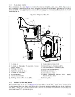
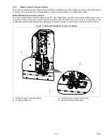
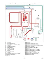
Figure 3.4 Air Cooled Condenser Section
1) Micro Channel Heat Exchanger (MCHE) Coil
2) Grille and Venturi Assembly
3) Condenser Fan
4) Condenser Coil Cover
5) Condenser Fan Motor
6) Receiver
7) Receiver Sight Glass*
8) Receiver Moisture & Liquid Indicator*
9) Fusible Plug
10) Filter Drier
11) Economizer
12) Economizer Solenoid Valve (ESV)
13) Economizer Expansion Valve (EXV)
14) Service Access Valve
- - - - -
* Not visible in view, located behind Filter Drier.
Содержание PrimeLINE 69NT40-571-001
Страница 2: ......
Страница 4: ......
Страница 14: ......
Страница 36: ......
Страница 110: ......
Страница 116: ......
Страница 171: ...8 1 T 372 SECTION 8 ELECTRICAL WIRING SCHEMATIC AND DIAGRAMS Figure 8 1 Legend Standard Unit Configuration ...
Страница 172: ...T 372 8 2 ELECTRICAL WIRING SCHEMATIC AND DIAGRAMS Figure 8 2 Schematic Diagram Based on Drawing 62 11957 ...
Страница 176: ......
Страница 178: ......
Страница 180: ......
Страница 184: ......
Страница 185: ......