


4–45
T-372
Troubleshooting
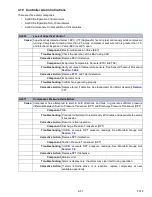
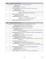
Test the CPDS. See Sensor Checkout Procedure,
.
Corrective Action
Replace the CPDS if defective. See Sensor Replacement
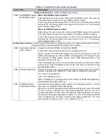
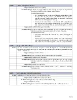
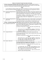
AL265
Discharge Pressure Transducer (DPT) Fault
Cause:
Compressor Discharge Pressure Transducer (DPT) is out of range.
Component
Discharge Pressure Transducer (DPT)
Troubleshooting
Confirm accurate DPT pressure readings. See Manifold Gauge Set
Corrective Action
Replace DPT if defective.
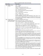
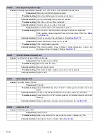
AL266
Suction Pressure Transducer (SPT), Evaporator Pressure Transducer (EPT) Fault
Cause:
Suction Pressure Transducer (SPT) or Evaporator Pressure Transducer (EPT) out of range.
Component
Suction Pressure Transducer (SPT); Evaporator Pressure Transducer (EPT)
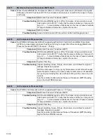
Troubleshooting
Confirm accurate SPT and EPT pressure readings. See Manifold Gauge
Set
. Performing a pre-trip 5-9 test will also check the
transducers.
Corrective Action
Replace SPT / EPT if defective.
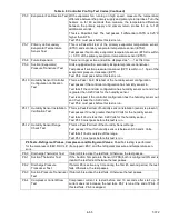
Troubleshooting
Monitor
Corrective Action
If the alarm persists, it may indicate a failing compressor. See Compressor
Service
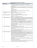
AL267
Humidity Sensor (HS) Fault
Cause:
Humidity Sensor (HS) reading out of range.
Component
Humidity Sensor (HS)
Troubleshooting
Make sure the HS is properly connected in the socket. Make sure the HS
wires have not been damaged.
Corrective Action
Monitor, replace HS if alarm persists.
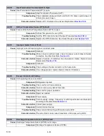
AL269
Evaporator Temperature Sensors (ETS1 / ETS2) Fault
Cause:
Evaporator Temperature Sensors (ETS1 / ETS2) out of range.
Component
Evaporator Temperature Sensors (ETS1 / ETS2)
Troubleshooting
Test the sensors. See Sensor Checkout Procedure
.
Corrective Action
Replace Evaporator Temperature Sensors (ETS1 / ETS2) if defective.
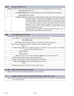
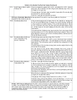
AL270
Supply Recorder Sensor (SRS) Fault
Cause:
Supply Recorder Sensor (SRS) is out of range.
Component
Supply Recorder Sensor (SRS)
Troubleshooting
Perform pre-trip P5.
Corrective Action
If P5 passes, no further action is required. If P5 fails, replace the defective
sensor as determined by P5. See Temperature Sensor Service
AL264
Discharge Temperature Sensor (CPDS) Fault
Содержание PrimeLINE 69NT40-571-001
Страница 2: ......
Страница 4: ......
Страница 14: ......
Страница 36: ......
Страница 110: ......
Страница 116: ......
Страница 171: ...8 1 T 372 SECTION 8 ELECTRICAL WIRING SCHEMATIC AND DIAGRAMS Figure 8 1 Legend Standard Unit Configuration ...
Страница 172: ...T 372 8 2 ELECTRICAL WIRING SCHEMATIC AND DIAGRAMS Figure 8 2 Schematic Diagram Based on Drawing 62 11957 ...
Страница 176: ......
Страница 178: ......
Страница 180: ......
Страница 184: ......
Страница 185: ......