background image

© 2014, Carmanah Technologies Corporation. June 2014. 61249_M650H_User_Manual_RevC

M650H USER MANUAL

30

Logging In

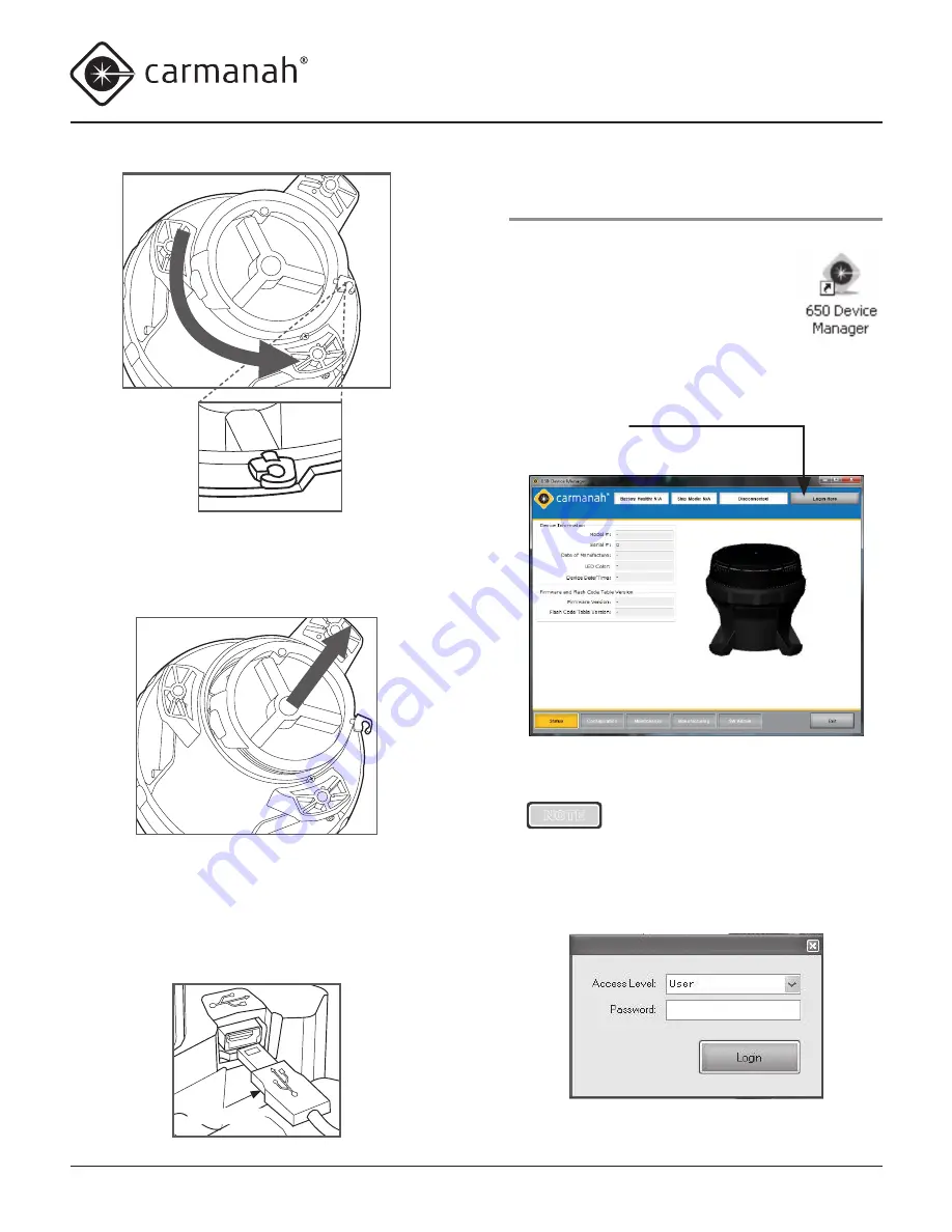
To login to the 650DM software:

1.  From either the 

Start/Program

 menu 

or your Windows Desktop, click 

650 

Device Manager


The 

650 Device Manager Status

 screen appears.

2.  From the 

650 Device Manager Status

 screen, click 

Login Here

.

The 

Login

 dialog box appears.

NOTE

You can disconnect your USB cable 

from a lantern and reconnect to 

another lantern without logging out 

of the 650DM. The 650DM will take 

a few seconds to connect to the  

new lantern.

4.  Lift the cover out using the protruding locking tab. 

You can now access the USB connector port (for 

using the 650DM software).

5.  Using the USB cable provided with your 650 

Device Manager software, connect the larger end 

to an available USB connector in your computer. 

Connect the other smaller end to the USB 

connector inside the M650H.

USB cable

Содержание M650H

Страница 1: ...ogies Corporation June 2014 61249_M650H_User_Manual_RevC USER MANUAL Technical Support Email customerservice carmanah com Toll Free 1 877 722 8877 US Canada Worldwide 1 250 380 0052 Fax 1 250 380 0062 Web carmanah com M650H ...

Страница 2: ...d person s in accordance with all applicable local codes and standards Equipment shall be positioned outside the 5m vicinity of a compass as per ISO 694 Safety and Usage Precautions WARNING The M650H s Battery Pack contains lead lead compounds and other compounds known to the State of California to cause cancer and reproductive harm Please handle with care and wash your hands thoroughly after hand...

Страница 3: ...ode 19 Standard On Mode 19 Fog Mode 20 Infrared Remote Programmer Optional 20 Battery Pack 21 Battery Pack Health Status 21 Charging the Battery Pack 21 Solar Charging 21 Optional Plug In Charger 21 Charging with an Artificial Light Source 22 Preserving Battery Pack Health 22 Storage Procedures 23 Replacing the Battery Pack 23 Maintenance 25 Recycling 26 The Battery Pack 26 Shipping 27 Ship Mode 2...

Страница 4: ...ng the Passcode 57 Changing the Flash Code 58 Turning the M650H Off 59 Setting the M650H to Ship Mode 59 Restoring the M650H from Ship Mode 60 Determining the Battery Pack s State of Health 60 Appendix C Accessories 61 M650H Accessories 61 Appendix D Specifications 62 Form Factor 62 Optical 62 Energy Capture 62 Flash Synchronization Optional 62 Energy Storage 62 User Interface 62 Standards and Tes...

Страница 5: ...na and dock Lighting Port lighting Oil and offshore platforms Channel boundaries River mouths Marina entrances Extended structures such as aquaculture floats or breakwaters The M650H is available with optional GPS flash synchronization Like Carmanah s larger GPS equipped solar marine lanterns the M650H uses the precise timing signal of GPS satellites to synchronize its flash pattern with other M65...

Страница 6: ... OBUI Optional On Off Switch Optional Infrared Programmer 650 Device Manager software via USB cable Has multiple layers of programmable password protection Is available in red green yellow white and blue LED output colours Is designed in accordance with the European Union s guidelines for the Restriction of Hazardous Substances in electronic equipment RoHS ...

Страница 7: ...ndicator identification label lens mounting foot BOTTOM VIEW SIDE VIEW INTERNAL VIEW BOTTOM COVER REMOVED pressure equalizing vent battery connector USB port battery strap battery strap tab on board interface user interface display set button selector buttons optional on off switch bottom cover locking tab and screw removable bottom cover mounting hole M650H Parts Description ...

Страница 8: ...nsert the short L shaped end through the small hole in the top of one of the M650H mounting feet 2 Rotate the wire upwards 90 degrees until it is in the upright position 3 Twist the Bird Deterrent clockwise until the L shaped end snaps into the groove on the bottom of the mounting foot The Bird Deterrent extends over the top of the M650H to prevent birds from landing on the M650H NOTE The M650H ca...

Страница 9: ...ion slide the switch to the right until it snaps into position In the On position a I symbol is visible on the switch 2 To put the switch in the Off position slide the switch to the left until it snaps into position In the Off position a O symbol is visible on the switch NOTE Removing the bottom cover is equivalent to placing the switch in the On position Bottom Cover Lock You can lock or unlock t...

Страница 10: ... minimize its exposure to high temperatures Choose a location that is away from hot dark coloured surfaces like asphalt or black steel plate Carmanah offers mounting kits that can help reduce the temperature of your Battery Packs allowing longer replacement intervals Installing the M650H The M650H has three mounting feet with holes for M6 fasteners fasteners are not included and can be ordered as ...

Страница 11: ...change passcodes update firmware etc You can perform some basic configuration using The optional On Off Switch Detailed information about using the On Off Switch is located on pages 8 and 19 of this document You do not have to remove the Bottom Cover to use the On Off Switch The optional Infrared Remote Programmer IR Remote Detailed information about using the IR Remote is located in Appendix B Yo...

Страница 12: ...tus pg 21 2 FLSH programmed Flash code pg 14 3 Int programmed effective intensity in candela pg 14 4 ALC Automatic Light Control ALC status on or off pg 15 5 Date current date pg 15 6 Info programmed firmware version pg 33 7 Lat programmed latitude setting pg 50 8 Long programmed longitude setting pg 50 9 GPS GPS receiver status pg 16 GPS enabled lanterns only 10 vBat Actual battery voltage in mil...

Страница 13: ...Entering the Passcode Before you can edit any of the M650H s parameters you must enter a Passcode The default Passcode is 753 To enter the Passcode 1 Press and hold the set button for approximately one second The words Pass Code briefly display on the OBUI followed by three zeroes with the left zero flashing The display is prompting you to enter the Passcode beginning with the first digit 2 Enter ...

Страница 14: ...ng the same procedure 7 When you are finished and the new Flash Code shows on the display press and hold the set button for approximately one second The code flashes three times quickly to indicate that the new Flash Code has been set The M650H will then demonstrate the new flash code for one minute NOTE If programmed in a dim location the M650H will continue to flash after one minute has elapsed ...

Страница 15: ...o toggle the ALC setting 1 Press the set button until the words Pass Code appear on the OBUI display 2 Enter the Passcode to log in to the M650H 3 After logging in press the up or down buttons until ALC appears on the display 4 Press and hold the set button until the current state of the ALC flashes either on or off 5 Press the up or down buttons to toggle ALC to off or on 6 Press the set button f...

Страница 16: ...r down button to enter the specific day of the month when dated shutdown will end 6 Press the set button for approximately one second to store the new reactivation date 5 While the year displays press the up or down button to change it 6 Press the set button briefly The month starts to flash on the OBUI display 7 While the month displays press the up or down button to change it 8 Press the set but...

Страница 17: ...he OBUI display displays the actual battery voltage in millivolts For example if the battery is 4 225 volts the display would show 4225 Fully charged is 4 3volts Fully discharged is 3 8 volts Resetting to Initial Settings Resetting to Initial Settings returns the M650H s configuration to the most recent settings 1 Press the set button until the words Pass Code appear on the OBUI display 2 Enter th...

Страница 18: ...re clean and in good condition Ensure that the inside surfaces of the M650H that the o rings will contact are also clean 2 If the Bottom Cover was difficult to remove apply a very thin coating of silicone o ring lubricant to the two o rings on the Bottom Cover before installing it 3 To install the Bottom Cover align it so that the protruding locking tab is aligned with the small angled wall in the...

Страница 19: ... the solar panel In GPS enabled lanterns the GPS receiver will enter the Pause state to conserve power To place the M650H in Off Mode move the On Off switch to the Off position The word OFF flashes three times on the display While in Off Mode the M650H continues to charge its battery pack when exposed to light but it will not respond to any infrared programming instructions Off NOTE If your M650H ...

Страница 20: ...ogrammed Flash Code and intensity regardless of ambient light conditions The M650H remains illuminated for the rest of that day and night turns off at dawn the next day and then operates in Standard On Mode The difference between Fog Mode and Standard On Mode is that when the switch is put into the On position with the lantern configured to operate in Fog Mode the M650H turns on and remains on for...

Страница 21: ...ge the M650H Battery Pack The Plug In Charger automatically charges the Battery Pack Like the on board charging system the Plug In Charger avoids overcharging the Battery Pack to prolong its life WARNING Charge the Battery Pack in a well ventilated cool spot Battery Pack Battery Pack Health Status The M650H periodically monitors the health of its Battery Pack There are four Battery Pack health sta...

Страница 22: ...ot produce enough solar energy to charge the Battery Pack Different light sources produce different charging times depending on the source wattage and spectral characteristics Do not place the light source too close to the M650H solar panel as very high temperatures can damage the lantern For example do not place the M650H closer than 12 30 cm to a 60 Watt light source 12 30 cm 60W NOTE Whenever p...

Страница 23: ...6 4 35 95 2 5 40 104 1 5 45 113 1 Do not store the M650H for long periods without charging the Battery Pack either with the optional Plug In Charger pg 21 or by placing it in the sun until the reported Battery Pack health is Good The amount of time it takes to charge in the sun depends on the installation location weather and the initial Battery Pack state of health Replacing the Battery Pack At t...

Страница 24: ...ody To install the Battery Pack follow the steps above in reverse Take care not to pinch any of the wires when seating the Bottom Cover after inserting a new Battery Pack NOTE When installing a new battery press and hold the Set button as you insert the battery connector into the M650H receptacle Continue to hold the Set button until Zero is displayed briefly This resets the M650H s Battery Pack h...

Страница 25: ... the M650H to ensure the solar panel has not been fouled by birds or covered in debris You can clean an M650H with water and a mild detergent Avoid any harsh detergents Pressure washing is a convenient way to clean the M650H and won t cause damage to the lantern Follow the guidelines below to pressure wash the M650H Use a 40 nozzle white Do not exceed 2900psi Keep the nozzle at least 6 15cm away f...

Страница 26: ...k When the M650H reports the Battery Pack s Health as bad the Battery Pack should be removed from the M650H and replaced with a new Battery Pack Consult carmanah com or your Carmanah dsitributor Bring the used Battery Pack to a lead acid battery collection or appropriate recycling facility DO NOT dispose of it in the garbage ...

Страница 27: ...ns on how to place the M650H into Ship Mode using the IR Remote Refer to Appendix A for instructions on how to place the M650H in Ship Mode using the 650 Device Manager software After the M650H enters Ship Mode place it into the box in which it is being stored or shipped and close the lid to ensure it stays in darkness The main LED remains off until the M650H is removed from the box and senses a d...

Страница 28: ...rk not yet installed on the computer 50 MB free disk space if Net framework already installed 32 bit colour 1024 X 768 minimum resolution One available USB port One USB cable Software Requirements Windows 7 Windows XP Service Pack 2 or 3 NOTE If your computer already has the Net framework installed the 650 Device Manager will install in a few seconds If the Net framework is not installed installat...

Страница 29: ...indow appears Congratulations you have successfully completed your 650 Device Manager installation NOTE If you have the older version 1 of 650 Device Manager installed the new version 2 will detect it and offer to uninstall it automatically before installing the new version 2 Removing the Bottom Cover Before you can connect the USB cable to the lantern you must remove the lantern s Bottom Cover To...

Страница 30: ... dialog box appears NOTE You can disconnect your USB cable from a lantern and reconnect to another lantern without logging out of the 650DM The 650DM will take a few seconds to connect to the new lantern 4 Lift the cover out using the protruding locking tab You can now access the USB connector port for using the 650DM software 5 Using the USB cable provided with your 650 Device Manager software co...

Страница 31: ...ck Login If you ve connected an M650H lantern to your computer using a USB cable then after a short pause the 650DM software connects to the lantern and a coloured picture of the M650H on the main screen replaces the darkened picture The picture that appears matches the LED colour of the M650H Once you successfully login several of the buttons in the Bottom Bar become active Inactive buttons displ...

Страница 32: ...plays Disconnected When connected to a lantern it displays the lantern s model name Login Here Logout Access Level Click this button to log out of 650DM The name in brackets indicates the access level of the user currently logged in to the device User Distributor or Manufacturing FUNCTION PAGE The centre area of the screen contains the Function Page information Different content appears in this ar...

Страница 33: ...the Status Page AREA NAME DESCRIPTION Device Information Area The Device Information Area contains the following information Model the lantern s model number Serial the lantern s serial number Date of Manufacture the date the lantern was manufactured LED Colour the colour of the LED in the lantern Device Date Time the date and time currently programmed on the lantern Firmware and Flash Code Table ...

Страница 34: ...Setting Columns shown in solid line boxes below indicate the 650DM s current setpoints The columns under the Device headings the Device Columns shown in dashed line boxes below show the connected lantern s settings The general method for changing a setting involves changing the 650DM setpoint s in the Setting Columns and then sending the setting s to the lantern using the Send Settings to Device b...

Страница 35: ...h you can change the Switch Mode between Standard Mode Std and Fog Mode Fog For more information about the Switch Mode refer to the table on page 40 Set Device Passcodes User Passcode This is the passcode that users enter when logging into a lantern using the On Board User Interface OBUI You can edit the passcode by typing in the desired setting or using the up down arrows Distributor Passcode Thi...

Страница 36: ... to put the lantern into Ship Mode Set Ship Mode On or take the lantern out of Ship Mode Set Ship Mode Off For more information on Ship Mode refer to the Ship Mode section of this Appendix Config Actions Send Settings to Device This sends the settings currently shown in the Setting Columns to the lantern Note that this button becomes inactive when the values in the Setting Columns would require mo...

Страница 37: ...tion tab and to set the 650DM login password s Security tab AREA NAME DESCRIPTION Connection Tab Connection Status The Connection Status field indicates if you are currently connected or not connected to a lantern Com Port The Com Port field displays the current communications port through which the lantern is connected to the 650DM Connection Tab 650DM Version This field displays the version of t...

Страница 38: ...Password Change area appears This allows you to change the password that is entered when you login to the 650DM To set a new password select the appropriate Access Level from the Access Level drop down menu enter the new password in the Password field and click Set Password NOTE If you are logged in as a User you will only see the Access Level User If you are signed in as a Distributor you will se...

Страница 39: ...ive Intensity setting ALC Automatic Light Control When ALC is enabled the lantern monitors the battery pack s state of charge and reduces the intensity level if the lantern is not receiving sufficient solar charging to maintain the battery pack When the battery pack recovers ALC automatically resumes operation at the programmed Effective Intensity If the lantern s latitude and longitude are set co...

Страница 40: ...ired the up down arrows to select your preferred User Passcode Set Device Time This sets the internal clock on your lantern to be the same as the time on your computer NOTE The M650H is equipped with an algorithm that uses daily transition events to periodically correct for its clock drifting over time It s not critical that the internal lantern clock and computer times be identical the internal l...

Страница 41: ... page to the lantern Get Settings From Device Click this to retrieve the lantern s current settings and copy them into the Setting column Note that when 650DM connects to a lantern it does this automatically Use the Get Settings From Device button if you have modified the values in the Setting columns of the Configuration page but don t want to send the settings to the lantern With the lantern plu...

Страница 42: ...d connect to the lantern 4 Click Configuration on the Bottom Bar The Configuration screen appears 5 Click Restore Defaults on the right side of the screen The lantern s current settings are replaced with the settings last programmed by your Distributor or Carmanah Manufacturing Using the Derived Values Derived Values are calculated based on the settings you select for your lantern The values descr...

Страница 43: ... you lower the Effective Intensity setting the Range value decreases Peak Intensity This is the intensity brightness of the beam when the LED is on This value is expressed in candela The Peak Intensity gives the intensity of the beam in the horizontal plane If you change the Effective Intensity setting the Peak Intensity value updates accordingly If you ve increased the Effective Intensity setting...

Страница 44: ...2 Connect the other end of the USB cable to an empty USB port on your computer 3 Open 650DM on your computer 650DM may take a moment to find and connect to the lantern 4 Click Configuration on the Bottom Bar The Configuration screen appears 5 Click Set Ship Mode On on the right side of the screen To confirm that the lantern is in Ship Mode Ship Mode On appears in the middle of the top bar To take ...

Страница 45: ...mputer Time and Device Time fields should match Setting the Day to Night Transition Level The Day to Night Transition Level D2N is the ambient brightness in lux at which the lantern will turn on in the evening A higher value for the D2N Transition Level causes the lantern to turn on earlier a lower value causes it to turn on later NOTE Remember that the earlier the lantern turns on the more batter...

Страница 46: ...a change to reflect the effect of the new N2D Transition Level 6 Click Send Setting to Device The new N2D Transition value is sent to the lantern The values for Autonomy and the Effective Intensity Limit in the Device column of the Derived Values area change to reflect the effect of the new N2D Transition Level Setting the ALC When ALC Automatic Light Control is enabled the lantern monitors the ba...

Страница 47: ...word 7 Click Set Password Your new password is now active Understanding the Installation Location Environmental Parameters 650DM displays information about the lantern s installation location based on its programmed geography settings latitude longitude and atmospheric transmissivity The lantern uses these parameters among others to calculate the lantern s Effective Intensity Limit The calculated ...

Страница 48: ...utor or Manufacturing access Logging In When logging in as a Distributor click Login Here select Distributor from the Access Level drop down enter your Distributor password and click Login After logging in as a Distributor you will have access to the Maintenance page Also other areas of the Configuration page become editable The Maintenance Page is available to a Distributor but not a User ...

Страница 49: ...ributor but not a User The Distributor Passcode field also becomes editable Configuring the M650H The Distributor uses the same procedures as a User to configure an M650H lantern Refer to User section for details on how to configure the lantern s basic settings The following procedures describe the configuration options that are not available to someone with a User Access Level ...

Страница 50: ...the Deployment Location 1 Remove the lantern s Bottom Cover and plug the USB cable into the USB port 2 Connect the other end of the USB cable to an empty USB port on your computer 3 Open 650DM on your computer 650DM may take a moment to find and connect to the lantern 4 Click Configuration on the Bottom Bar The Configuration screen appears 5 In the Geography area enter the latitude and longitude w...

Страница 51: ...e Device Access settings The checkboxes in the Device column indicate the lantern s current configuration Downloading a Configuration After you finish customizing the lantern s settings or open a Configuration File click Send Setting to Device This takes the values that are in the Setting columns and sends them to the lantern After sending the settings to the lantern the information in the Device ...

Страница 52: ...ile is saved in DCF format You can now download this Configuration File to as many lanterns as you would like Reading a Configuration File If you have several Configuration Files stored on your computer you can open each file to determine the differences between them Each Configuration File contains settings for the following parameters Flash Code Effective Intensity Automatic Light Control D2N Tr...

Страница 53: ...rn s settings will be copied into the Settings boxes Saving a Configuration File If you configure one lantern exactly how you want it and would like to copy this configuration over to other lanterns you can save the original lantern s Configuration File and then copy the file over to the other lanterns You can also save a lantern s Configuration File just so you have a record of how the lantern is...

Страница 54: ... the requested Passcode in the User Passcode field 4 Click Send Settings To Device The updated settings are sent to the lantern The next time someone tries to access the lantern they will need to know the new Passcode Updating the Firmware Occasionally it may be useful to be able to update new firmware to an M650H lantern These files when necessary will be supplied by Carmanah Technologies NOTE If...

Страница 55: ... by Carmanah Technologies To update the Flash Code Table on a lantern 1 Put the supplied Flash Code Table file csv exten sion in a suitable location on your hard drive 2 Remove the lantern s Bottom Cover and plug the USB cable into the USB port 3 Connect the other end of the USB cable to an empty USB port on your computer 4 Open 650DM on your computer 650DM may take a moment to find and connect to...

Страница 56: ...n use for diagnostic purposes To obtain a Datalog from a lantern 1 Remove the lantern s Bottom Cover and plug in the USB cable to the USB port 2 Connect the other end of the mini USB cable to an empty USB port on your computer 3 Open 650DM on your computer 4 Click Maintenance on the Bottom Bar The Maintenance page appears 5 In the Datalogs area click Get Datalog From Device The Browse For Folder d...

Страница 57: ... Enter Off Mode Entering the Passcode You must enter a Passcode before you can access any of the IR Remote features To enter the Passcode 1 Point the IR Remote at the side of the M650H 2 Press and hold any button for approximately three seconds The right most decimal point on the OBUI illuminates steadily to indicate it received the IR signal and entered IR Edit Mode In IR Edit Mode the main LED i...

Страница 58: ... s flashing pattern Refer to Appendix F for a complete list of the available Flash Codes To change the existing Flash Code 1 After entering the Passcode point the IR Remote at the side of the M650H lens and then press the Start button on the IR Remote 2 Enter the new Flash Code by pressing the three digits of the new Flash Code on the IR Remote The main LED flashes once each time the M650H receive...

Страница 59: ...nd to infrared commands Setting the M650H to Ship Mode If you are storing an M650H or have to return it to your distributor for maintenance or repair it is best to put the M650H into Ship Mode or Off mode When the M650H exits Ship Mode and returns to normal operation it will remember its Flash Code intensity and other settings To set the M650H to Ship Mode 1 After entering the Passcode point the I...

Страница 60: ...he M650H begins to operate automatically in dusk to dawn mode NOTE Check the M650H s Flash Code before deploying it If the Flash Code is set to 000 it indicates that the M650H is in Off mode and the main LED will not turn on even with the arrival of dusk Determining the Battery Pack s State of Health You can use the IR Remote to check the M650H s Battery Pack s state of health 1 After entering the...

Страница 61: ...nting plate when added security is a consideration Ideal for single unit installations each package contains the necessary items to properly mount one lantern Part list includes Nut security 20 trident 3 Driver for trident 20 nut 1 Driver hex security bit 876 770 Spaenaur 1 Washer flat SS 9 Screw security button head 20 x 1 5 SS 3 M650H Security Bolt Kit Excludes Drivers Part 56578 The M650H Secur...

Страница 62: ...rse Polarity Protection Yes Solar Panel Bypass Diodes Yes Solar Panel Blocking Diode Function Yes Flash Synchronization Optional GPS Internal GPS Receiver with rapid signal lock Energy Storage Replaceable Battery Pack Yes tool less Secured Battery Pack Yes Strap material meets ASTM D2000 2BG613 F7 G21 Vented Battery Pack Compartment Yes Battery Status Feedback Good Charge Low Bad Replace and actua...

Страница 63: ...Tested to MIL STD 810G Method 505 5 Procedure II 1120 W m2 44 C RF EMI Resilience Tested to EN 60945 2002 EN 61000 4 3 1995 100MHz 1GHz 10V m and 1GHz 12GHz 200V m Battery Life Tested equivalent to IEC 61427 Patents US 6 573 659 and other US Canadian EU patents pending Mounting Mounting bolt size 0 25 inch 6mm or 7mm Mounting foot thickness 0 5 inch 12 7mm Mounting bolt torque minimum 4 lbf ft 5 4...

Страница 64: ...C M650H USER MANUAL 64 Photometric Plots 0 5 10 15 20 25 30 35 40 45 50 55 60 65 8 7 6 5 4 3 2 1 0 1 2 3 4 5 6 7 8 Green Yellow White Red Blue NOTE Peak IALA intensity dependent on location Plot based on equatorial location of 12 hour night duration and 21 duty cycle flash code ...

Страница 65: ... 5 7 9 Fl 2 15s 1 2 1 11 10 Fl 2 5s 0 5 1 0 5 3 11 Fl 2 5s 1 1 1 2 12 Fl 2 6s 0 5 1 0 5 4 13 Fl 2 6s 0 8 1 2 0 8 3 2 14 Fl 2 6s 1 1 1 3 15 Fl 2 7s 1 1 1 4 16 Fl 2 8s 0 5 1 0 5 6 17 Fl 2 8s 1 1 1 5 18 Fl 2 1 10s 0 5 0 7 0 5 2 1 0 5 5 7 19 Fl 2 1 12s 0 8 1 2 0 8 2 4 0 8 6 20 Fl 2 1 12s 1 1 1 4 1 4 21 Fl 2 1 15s 1 2 1 5 1 5 22 Fl 2 1 6s 0 3 0 4 0 3 1 2 0 3 3 5 23 Fl 3 12S 0 5 2 0 5 2 0 5 6 5 24 Fl 3 ...

Страница 66: ... 5 0 5 1 5 0 5 1 5 0 5 8 5 35 Fl 4 15s 1 1 1 1 1 1 1 8 36 Fl 4 20s 0 5 1 5 0 5 1 5 0 5 1 5 0 5 13 5 37 Fl 5 20s 0 8 1 2 0 8 1 2 0 8 1 2 0 8 1 2 0 8 11 2 38 Fl 5 20s 1 1 1 1 1 1 1 1 1 11 39 Fl 6 15s 0 5 1 0 5 1 0 5 1 0 5 1 0 5 1 0 5 7 40 FL 5 1 1 1 41 FL 5 1 1 1 1 1 42 Fl 1 5s 0 3 1 2 43 Fl 1 5s 0 5 1 44 Fl 10s 0 5 9 5 45 Fl 10s 1 9 46 Fl 10s 1 5 8 5 47 Fl 12s 1 2 10 8 48 Fl 15s 1 14 49 Fl 2 5s 0 3...

Страница 67: ...4 3s 1 3 3 63 Fl 4 4s 0 4 4 64 Fl 4s 0 5 3 5 65 Fl 4s 0 8 3 2 66 Fl 4s 1 3 67 Fl 4s 1 5 2 5 68 Fl 5s 0 3 4 7 69 Fl 5s 0 5 4 5 70 Fl 5s 1 4 71 Fl 5s 1 5 4 5 72 Fl 6s 0 5 5 5 73 Fl 6s 0 6 5 4 74 Fl 6s 1 5 75 Fl 6s 1 5 3 5 76 Fl 7 5s 0 8 6 7 77 ISO 10S 5 5 78 ISO 2S 1 1 79 ISO 4S 2 2 80 ISO 5S 2 5 2 5 81 ISO 6S 3 3 82 ISO 8S 4 4 83 ISO 3S 1 5 1 5 84 LFL 10S 2 8 85 LFL 10S 3 7 86 LFL 10S 4 6 87 LFL 12...

Страница 68: ... MO U 10S 0 4 0 6 0 4 0 6 1 2 6 8 100 MO U 10S 0 5 0 5 0 5 0 5 1 5 6 5 101 MO U 15S 0 5 0 5 0 5 0 5 1 5 11 5 102 MO U 15S 0 6 0 3 0 6 0 3 1 4 11 8 103 MO U 15S 0 7 0 5 0 7 0 5 1 9 10 7 104 MO U 15S 0 7 0 7 0 7 0 7 2 1 10 1 105 MO U 15S 0 75 0 45 0 75 0 45 2 10 6 106 MO U 15S 1 15 0 73 1 15 0 73 3 03 8 21 107 MO U 15S 1 3 0 7 1 3 0 7 3 3 7 7 108 MO U 15S 0 75 0 15 0 75 0 15 1 65 11 55 109 MO U 15S ...

Страница 69: ...131 Q 1S 0 5 0 5 132 Q 1S 0 8 0 2 133 Q 2 10S 0 5 1 5 0 5 7 5 134 Q 2 10S 0 6 0 4 0 6 8 4 135 Q 2 5S 0 3 0 7 0 3 3 7 136 Q 2 6S 0 3 0 7 0 3 4 7 137 Q 2 6S 0 35 0 7 0 35 4 6 138 Q 3 10S 0 3 0 7 0 3 0 7 0 3 7 7 139 Q 3 10S 0 35 0 65 0 35 0 65 0 35 7 65 140 Q 3 10S 0 6 0 6 0 6 0 6 0 6 7 141 Q 4 10S 0 3 0 7 0 3 0 7 0 3 0 7 0 3 6 7 142 Q 4 12S 0 3 0 7 0 3 0 7 0 3 0 7 0 3 8 7 143 Q 4 15S 0 35 0 7 0 35 0...

Страница 70: ...0 35 0 65 0 35 0 65 0 35 0 65 0 35 0 65 0 35 0 65 0 35 6 65 156 Q 9 15S 0 6 0 6 0 6 0 6 0 6 0 6 0 6 0 6 0 6 0 6 0 6 0 6 0 6 0 6 0 6 0 6 0 6 4 8 157 VQ 0 5S 0 15 0 35 158 VQ 0 5S 0 2 0 3 159 VQ 0 6S 0 2 0 4 160 VQ 0 6S 0 3 0 3 161 VQ 3 5S 0 15 0 35 0 15 0 35 0 15 3 85 162 VQ 3 5S 0 2 0 3 0 2 0 3 0 2 3 8 163 VQ 3 5S 0 3 0 3 0 3 0 3 0 3 3 5 164 VQ 6 LFL 10S 0 2 0 3 0 2 0 3 0 2 0 3 0 2 0 3 0 2 0 3 0 2...

Страница 71: ...7s 0 5 1 5 0 5 4 5 184 Fl 3 9s 0 5 1 5 0 5 1 5 0 5 4 5 185 LFL 11s 2 9 186 Fl 6 1 15s 0 5 0 5 0 5 0 5 0 5 0 5 0 5 0 5 0 5 0 5 0 5 0 5 2 7 187 Mo 0 12s 1 5 0 5 1 5 0 5 1 5 6 5 188 Mo 0 15s 1 5 0 5 1 5 0 5 1 5 9 5 189 Q 1S 0 25 0 75 190 Q 3 4 6s 0 3 0 7 0 3 2 0 3 1 191 Fl 7 5s 0 5 7 192 Fl 4 11s 0 5 1 5 0 5 1 5 0 5 1 5 0 5 4 5 193 FL 3 21s 0 5 1 5 0 5 4 5 0 5 13 5 194 FL 3 6s 0 5 0 5 0 5 0 5 0 5 3 5...

Страница 72: ... 0 2 0 4 0 2 0 4 0 2 3 6 216 VQ 6 LFL 10S 0 3 0 3 0 3 0 3 0 3 0 3 0 3 0 3 0 3 0 3 0 3 0 3 3 3 4 217 VQ 9 10S 0 2 0 4 0 2 0 4 0 2 0 4 0 2 0 4 0 2 0 4 0 2 0 4 0 2 0 4 0 2 0 4 0 2 5 218 OC 3 12S 4 5 1 5 1 5 1 5 1 5 1 5 219 OC 4 12S 5 1 1 1 1 1 1 1 220 FL 3 12S 1 1 5 1 1 5 1 6 221 FL 4 15S 1 1 5 1 1 5 1 1 5 1 6 5 222 FL 5 20S 1 1 5 1 1 5 1 1 5 1 1 5 1 9 223 MO A 1 1 3 7 224 FL 5 20S SADO 0 5 1 5 0 5 1...

Страница 73: ...0 5 2 5 240 CST11 0 3 0 7 0 3 2 7 241 CST12 6 6 242 CST13 2 1 5 1 243 CST14 0 4 0 6 0 4 0 6 0 4 2 6 244 CST15 0 8 1 0 8 1 0 8 1 0 8 1 0 8 2 245 CST16 0 8 1 0 8 1 0 8 1 0 8 3 8 246 CST17 0 5 0 5 0 5 0 5 0 5 5 5 247 CST18 0 5 2 5 0 5 2 5 0 5 2 5 0 5 10 5 248 CST19 0 8 5 2 249 CST20 0 8 6 2 250 CST21 0 5 2 0 5 2 0 5 2 0 5 8 251 Fl 3 5s 0 7 2 8 252 Fl 3 6s 0 7 2 9 253 Fl 5 5s 0 7 4 8 254 Fl 3 15s 0 5 ...

Страница 74: ...t night time with no background light Visibility is a function of atmospheric transmissivity Typically transmissivity T 0 74 and V 18520 m 10 NM At equatorial latitudes and clear skies T 0 85 and V 34262 m 18 5 NM Night Time Range and Intensities RANGE NM EFFECTIVE INTENSITY cd T 0 74 T 0 85 0 5 0 2 0 2 0 6 0 3 0 3 0 7 0 4 0 4 0 8 0 6 0 5 0 9 0 7 0 6 1 0 0 9 0 8 1 1 1 2 1 0 1 2 1 4 1 2 1 3 1 7 1 4...

Страница 75: ...6 5 205 83 6 6 218 87 6 7 232 91 6 8 246 96 6 9 261 100 7 0 277 105 Effective Intensity The effective intensity of a flashing lantern comes from the following calculation known as Schmidt Clausen or Blondel Rey documented in IALA Recommendations E 122 2001 and E 200 4 2008 This method is valid for the rectangular non fluctuating flash profiles below the flicker fusion frequency 60 Hz used by Carma...

Страница 76: ... of your M650H please contact your distributor for troubleshooting and technical support Customer Service Before contacting Carmanah s Customer Service department please have the serial number of your M650H available a brief description of the problem as well as all details of installation storage and recharging efforts To contact Carmanah s Customer Service Department Mail Carmanah Technologies C...

Страница 77: ... 2014 Carmanah Technologies Corporation June 2014 61249_M650H_User_Manual_RevC M650H USER MANUAL 77 This page is intentionally blank ...

Страница 78: ...June 2014 61249_M650H_User_Manual_RevC 78 2014 Carmanah Technologies Corporation carmanah com Technical Support Email customerservice carmanah com Toll Free 1 877 722 8877 US Canada Worldwide 1 250 380 0052 Fax 1 250 380 0062 Web carmanah com ...

Отзывы: