Carel EVD Evolution Twin Скачать руководство пользователя страница 20

ENG

“EVD Evolution TWIN” +0300006EN - rel. 2.6 - 31.01.2019

20

5. CONTROL

S

uperheat control

The parameter that the control of the electronic valve is based on is the 
superheat temperature, which effectively tells whether or not there is liquid 
at the end of the evaporator. EVD Evolution twin can independently manage 
superheat control on two refrigerant circuits. The superheat temperature 
is calculated as the difference between: superheated gas temperature 
(measured by a temperature probe located at the end of the evaporator) and 
the saturated evaporation temperature (calculated based on the reading of a 
pressure transducer located at the end of the evaporator and using the Tsat(P) 
conversion curve for each refrigerant).

Superheat = Superheated gas temperature(*) – Satur. evaporation temperature
(*) suction

If the superheat temperature is high it means that the evaporation process is 
completed well before the end of the evaporator, and therefore flow-rate of 
refrigerant through the valve is insufficient. This causes a reduction in cooling 
efficiency due to the failure to exploit part of the evaporator. The valve must 
therefore be opened further. Vice-versa, if the superheat temperature is low 
it means that the evaporation process has not concluded at the end of the 
evaporator and a certain quantity of liquid will still be present at the inlet to 
the compressor. The valve must therefore be closed further. The operating 
range of the superheat temperature is limited at the lower end: if the flow-
rate through the valve is excessive the superheat measured will be near 0 K. 
This indicates the presence of liquid, even if the percentage of this relative to 
the gas cannot be quantified. There is therefore un undetermined risk to the 
compressor that must be avoided. Moreover, a high superheat temperature 
as mentioned corresponds to an insufficient flow-rate of refrigerant. The 
superheat temperature must therefore always be greater than 0 K and have 
a minimum stable value allowed by the valve-unit system. A low superheat 
temperature in fact corresponds to a situation of probable instability due to 
the turbulent evaporation process approaching the measurement point of 
the probes. The expansion valve must therefore be controlled with extreme 
precision and a reaction capacity around the superheat set point, which will 
almost always vary from 3 to 14 K. Set point values outside of this range are 
quite infrequent and relate to special applications.

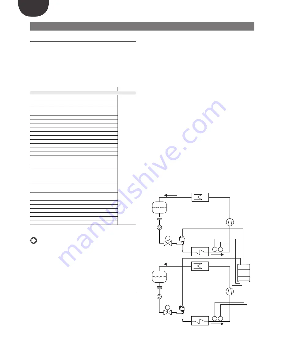
Example of superheat control on two independent circuits A and B

.

S2

S1

EVD evolution

twin

PA

E1

V1

S1

F1

L1

M

TA

CP1

C1

EEVA

PB

E2

V2

S2

F2

L2

M

TB

CP2

C2

EEVB

S3

S4

A

B

Fig. 5.a

5.1 Main 

control

EVD evolution twin features two types of control, which can be set 
independently for driver A and B.  Main control defines the operating mode 
of the driver. The first 10 settings refer to superheat control, the others are so-
called “special” settings and are pressure or temperature settings or depend 
on a control signal from an external controller. The last special functions (18, 
19, 20) also relate to superheat control, but they can be selectable if EVD 
Evolution TWIN is working as single driver  (see Appendix 2). Programmable 
control exploits CAREL’s technology and know-how in terms of control 
logic. Finally, it is possible to control liquid level in applications with flooded 
evaporator/condenser.

Parameter/Description

Def.

CONFIGURATION
Main control

multiplexed 
showcase/
cold room

Superheat control

1= multiplexed showcase/cold room
2= showcase/cold room with compressor on board 
3= “perturbed” showcase/cold room 
4= showcase/cold room with sub-critical CO

2

5= R404A condenser for sub-critical CO

2

6= air-conditioner/chiller with plate heat exchanger 
7= air-conditioner/chiller with tube bundle heat exchanger
8= air-conditioner/chiller with finned coil heat exchanger
9= air-conditioner/chiller with variable cooling capacity
10= “perturbed” air-conditioner/chiller 

Special control

11= EPR back pressure
12= hot gas bypass by pressure 
13= hot gas bypass by temperature 
14= transcritical CO

2

 gas cooler 

15= analogue positioner (4 to 20 mA) 
16= analogue positioner (0 to 10 V)
17= air-conditioner/chiller or showcase/cold room with 
adaptive control
18= air-conditioner/chiller with Digital Scroll compressor (*)
19=AC/chiller with BLDC scroll compressor (CANNOT BE 
SELECTED)
20=superheat regulation with 2 temperature probes (CANNOT 
BE SELECTED)
21=I/O expander for pCO (**)
22= Programmable SH regulation
23= Programmable special regulation
24= Programmable positioner
25= Evaporator liquid level regulation with CAREL sensor
26= Condenser liquid level regulation with CAREL sensor
(*) only for CAREL valve drivers; (**) control only settable on driver A, howe-
ver corresponds to the entire controller.

Tab. 5.a

 Note:  

• 

R404A condensers with subcritical CO

2

 refer to superheat control for valves 

installed in cascading systems where the flow of R404A (or other refrigerant) 
in an exchanger acting as the CO

2

 condenser needs to be controlled;

• 

“perturbed” cabinet/cold room or air-conditioner/chiller refer to units 
that momentarily or permanently operate with swinging condensing or 
evaporation pressure;

• 

for the Auxiliary control setting see Appendix 2

The following paragraphs explain all the types of control that can be set on 
EVD evolution twin.

5.2 Superheat 

control

The primary purpose of the electronic valve is ensure that the flow-rate of 
refrigerant that flows through the nozzle corresponds to the flow-rate required 
by the compressor. In this way, the evaporation process will take place along 
the entire length of the evaporator and there will be no liquid at the outlet and 
consequently in the branch that runs to the compressor.
As liquid is not compressible, it may cause damage to the compressor and even 
breakage if the quantity is considerable and the situation lasts some time.

Содержание EVD Evolution Twin

Страница 1: ...OWER SIGNAL CABLES TOGETHER READ CAREFULLY IN THE TEXT I n t e g r a t e d C o n t r o l S o l u t i o n s E n e r g y S a v i n g s User manual Driver for 2 electronic expansion valves EVD evolution...

Страница 2: ......

Страница 3: ...he internal circuits and mechanisms may be irreparably damaged do not use corrosive chemicals solvents or aggressive detergents to clean the device do not use the product for applications other than t...

Страница 4: ......

Страница 5: ...6 Programmable control 26 5 7 Control with refrigerant level sensor 28 6 FUNCTIONS 29 6 1 Power supply mode 29 6 2 Battery charge delay 29 6 3 Network connection 29 6 4 Inputs and outputs 29 6 5 Cont...

Страница 6: ......

Страница 7: ...he serial port see paragraph 2 9 in place of the service serial port The universal models can drive all types of valves while the CAREL models only drive CAREL valves 1 1 Models Code Description EVD00...

Страница 8: ...bcooling measurement high condensing temperature protection HiTcond modulating thermostat subcooling measurement reverse high condensing temperature protection possibility to manage CO2 R744 cascade s...

Страница 9: ...N A CLOSE A OPEN B CLOSE B A B COMB NOB 1 3 2 4 A shield TRADRFE240 4 1 2 3 8 9 10 11 12 6 13 14 7 15 16 5 S B 17 18 CAREL EX V VALVE B CAREL EX V VALVE A EVD evolution twin Fig 2 c Key 1 green 2 yell...

Страница 10: ...lation environment Important avoid installing the controller in environments with the following characteristics relative humidity greater than the 90 or condensing strong vibrations or knocks exposure...

Страница 11: ...he twin 1 controller and the remote option for the other drivers Driver B on the twin3 controller must use another pressure probe P2 Example twin1 twin2 twin3 Probe S1 driver A 0 5 to 7 barg P1 remote...

Страница 12: ...EVD evolution twin can be connected to the computer updating the firmware at the same time each controller must have a different network address 2 10 Upload Download and Reset parameters display Proc...

Страница 13: ...DI2 VREF Tx Rx GND GND DI1 S4 S3 S2 S1 GND DI2 VREF 1 20 Tx Rx DI1 S4 S3 S2 S1 GND DI2 VREF L 2 Fig 2 o Key 1 green 21 black 2 yellow 22 blue 3 brown 23 computer for configuration supervision 4 white...

Страница 14: ...programming operations on the controller 3 2 Display and keypad The graphic display shows two variables for each driver A B the control status of the driver activation of the protectors any alarms an...

Страница 15: ...st figure and confirming each figure with ENTER 4 if the value entered is correct the first modifiable parameter is displayed network address 5 press UP DOWN to select the parameter to be set 6 press...

Страница 16: ...dby until re enabled with the valve stopped in the last position pCO PROGRAMMABLE CONTROLLER the first operation to be performed if necessary is to set the network address using the display Important...

Страница 17: ...arameter in question if the valve and or the pressure probe used are not available in the list select any model and end the procedure Then the controller will be enabled for control and it will be pos...

Страница 18: ...the same type A ratiometric probe and an electronic probe cannot be used together Note in the case of multiplexed systems where the same pressure probe is shared between the twin1 and twin2 controller...

Страница 19: ...commissioning After commissioning check that the valves complete a full closing cycle to perform alignment set if necessary in Service or Manufacturer programming mode the superheat set point otherwis...

Страница 20: ...ver The first 10 settings refer to superheat control the others are so called special settings and are pressure or temperature settings or depend on a control signal from an external controller The la...

Страница 21: ...0 can be used shared between driver A and B Ratiometric transducers cannot be shared Another possibility involves connecting two equal valves operation in parallel mode see paragraph 2 5 to the same e...

Страница 22: ...d by the user and involves just one optimisation procedure Both procedures give new values to the PID superheat control and protection function parameters PID proportional gain PID integral time PID d...

Страница 23: ...ing Digital Scroll compressors allow wide modulation of cooling capacity by using a solenoid valve to active a patented refrigerant bypass mechanism This operation nonetheless causes swings in the pre...

Страница 24: ...temperature This control function can be used to control cooling capacity which in the following example is performed by driver B On a refrigerated cabinet if the ambient temperature probe S4 measures...

Страница 25: ...V1 Solenoid valve For the wiring see paragraph General connection diagram This involves PID control without any protectors LowSH LOP MOP see the chapter on Protectors without any valve unblock proced...

Страница 26: ...and receives the information needed to manage the valves from the pCO Parameter Description Def CONFIGURATION Main control I O expander for pCO multiplexed showcase cold room Tab 5 l TA PA S1 EVD evo...

Страница 27: ...mmable control input The function assigned to each input is defined by parameter Programmable control input The parameter has 16 bits and is divided into 4 digits as described in Programmable control...

Страница 28: ...ent function f1 S1 f2 S2 f3 S3 f4 S4 Programmable control input_1 4100 Measurement Tdew S1 S2 Programmable control options_1 2140 1 S1 Evaporation pressure 2 S2 Suction temperature 3 S3 Condensing pre...

Страница 29: ...d S4 as well as the possibility to calibrate the pressure and temperature signals As regards the choice of pressure liquid probe S1 and S3 see the chapter on Commissioning Inputs S2 S4 The options are...

Страница 30: ...EC PRIM SEC 1 PRIM PRIM DI1 DI2 2 PRIM SEC DI1 DI2 DI1 3 SEC PRIM DI2 DI2 DI1 4 SEC SEC Regulation backup driver A supervisor variable DI1 Regulation backup driver B supervisor variable DI2 Note that...

Страница 31: ...when the compressor stops or the control solenoid valve closes The valve is closed or open according to the setting of Valve open in standby The percentage of opening is set using Valve position in s...

Страница 32: ...dby T1 Pre position time P Pre positioning T2 Start delay after defrost R Control t Time Positioning change cooling capacity This control status is only valid for the pLAN controller If there is a cha...

Страница 33: ...closed or fully open position the valve may physically not be in that position The Synchronisation procedure allows the driver to perform a certain number of steps in the suitable direction to realig...

Страница 34: ...on of the protector LowSH low superheat The protector is activated so as to prevent the return of liquid to the compressor due to excessively low superheat values Parameter description Def Min Max UOM...

Страница 35: ...e trying to stop the superheat from increasing as much as possible Normal operating conditions will not resume based on the activation of the protector but rather on the reduction in the refrigerant c...

Страница 36: ...17 Danfoss ETS 250 5 Alco EX7 18 Danfoss ETS 400 6 Alco EX8 330Hz recommend CAREL 19 Two EX V CAREL connected together 7 Alco EX8 500Hz specific Alco 20 Sporlan SER I G J K 8 Sporlan SEI 0 5 11 21 Da...

Страница 37: ...24 Programmable positioner 25 Evaporator liquid level regulation with CAREL sensor 26 Condenser liquid level regulation with CAREL sensor only for controls for CAREL valves common parameter between d...

Страница 38: ...city 4 Set point control 5 Superheat 6 Suction temperature 7 Evaporation temperature 8 Evaporation pressure 9 Condensing temperature 10 Condensing pressure 11 Modulating thermostat temperature 12 EPR...

Страница 39: ...e S1 MINIMUM alarm value 200 2900 barg psig A 37 36 CO C S2 calibration offset 0 20 36 20 20 36 20 C F volt A 41 40 CO C S2 calibration gain 0 to 10 V 1 20 20 A 43 42 CO C Temperature S2 MINIMUM alarm...

Страница 40: ...A HiTcond threshold SELECT WITH PROG CONT 80 85 121 200 392 C F A 58 57 C HiTcond integral time SELECT WITH PROG CONT 20 0 800 s A 57 56 A Modulating thermostat set point SELECT WITH PROG CONT 0 85 12...

Страница 41: ...57 32768 32767 I 129 256 Bubble f low 17253 32768 32767 I 130 257 C Faulty closure alarm status 0 1 no yes 0 0 1 D 49 48 C Battery charge delay 0 0 250 min I 135 262 CO ALARM CONFIGURATION C Low super...

Страница 42: ...s ETS 250 5 Alco EX7 18 Danfoss ETS 400 6 Alco EX8 330Hz recommend CAREL 19 Two EX V CAREL connected together 7 Alco EX8 500Hz specific Alco 20 Sporlan SER I G J K 8 Sporlan SEI 0 5 11 21 Danfoss CCM...

Страница 43: ...rammable positioner 25 Evaporator liquid level regulation with CAREL sensor 26 Condenser liquid level regulation with CAREL sensor control only settable on driver A however corresponds to the entire c...

Страница 44: ...acity 4 Set point control 5 Superheat 6 Suction temperature 7 Evaporation temperature 8 Evaporation pressure 9 Condensing temperature 10 Condensing pressure 11 Modulating thermostat temperature 12 EPR...

Страница 45: ...ssure S1 MINIMUM alarm value 200 2900 barg psig A 37 36 CO C S2 calibration offset 0 20 36 20 20 36 20 C F volt A 41 40 CO C S2 calibration gain 0 to 10 V 1 20 20 A 43 42 CO C Temperature S2 MINIMUM a...

Страница 46: ...ROG CONT 80 85 121 200 392 C F A 58 57 CO C HiTcond integral time SELECT WITH PROG CONT 20 0 800 s A 57 56 CO A Modulating thermostat set point SELECT WITH PROG CONT 0 85 121 200 392 C F A 61 60 CO A...

Страница 47: ...suction temperature alarm threshold 50 85 121 200 392 C F A 97 96 C Low suction temperature alarm delay 0 alarm disabled 300 0 18000 s I 65 192 VALVE C EEV minimum steps 50 0 9999 step I 66 193 C EEV...

Страница 48: ...A 111 110 R Liquid regulation evaporator condenser level percentage 0 0 100 A 116 115 R Valve position 0 0 9999 I 4 131 R Current unit cooling capacity 0 0 100 I 7 134 R W Adaptive control status 0 1...

Страница 49: ...cooling capacity 0 0 100 I 50 177 R W EVD status 0 0 20 I 51 178 R Protector status 0 0 5 I 52 179 R Control mode 1 1 26 I 73 200 R W Adaptive control status 0 0 6 I 77 204 R Last tuning result 0 0 8...

Страница 50: ...ration pressure Condensing temperature Condensing pressure Modulating thermostat temperature EPR pressure back pressure Hot gas bypass pressure Hot gas bypass temperature CO2 gas cooler outlet tempera...

Страница 51: ...to the corresponding driver 3 press Help to display the required alarm queue the control alarms can be disabled by setting the corresponding delay to zero Table of alarms Type of alarm Cause of the al...

Страница 52: ...S3 alarm manage ment parameters Check the probe connections Check the parameters Probe S1 S3 alarm management and Pressure S1 S3 MINIMUM and MAXIMUM alarm values Temperature difference Maximum pressu...

Страница 53: ...rced to the initial position control stopped Parameter description Def Min Max UOM CONFIGURATION Probe S1 alarm management 1 No action 2 Forced valve closing 3 Valve in fixed position 4 Use backup pro...

Страница 54: ...ng powered up the controller forced closing of the valve is performed immediately Important after having resolved the problem with the motor it is recommended to switch the controller off and on again...

Страница 55: ...percussions on the control temperature Liquid returns to the com pressor only after defrosting for multiplexed showcases only The pause in control after defrosting is too short for MasterCase MasterCa...

Страница 56: ...culation in reference to the ratio between the rated cooling capacity of the evaporator and the capacity of the valve if necessary lower the value The unit switches off due to low pressure during cont...

Страница 57: ...n 0 1 fs measurement error 2 fs maximum 1 typical electronic pressure probe 4 to 20 mA resolution 0 5 fs measurement error 8 fs maximum 7 typical remote electronic pressure probe 4 to 20mA Maximum num...

Страница 58: ...12 a Then the user can choose to 1 directly access the list of parameters for the EVD evolution twin saved to EEPROM select tLAN This is done in real time ONLINE mode at the top right set the network...

Страница 59: ...code Different firmware versions may cause compatibility problems 12 4 Setting the default parameters When the program opens select the model from the range and load the associated list of parameters...

Страница 60: ...aporation pressure probe S1 and the suction temperature probe S2 which will be fitted after the evaporator and digital input 1 2 to enable control As an alternative to digital input 1 2 control can be...

Страница 61: ...o 20 mA probe and then manually modify the minimum and maximum measurement in the manufacturer parameters corresponding to the probes Important probes S3 and S4 are shown as NOT USED if the auxiliary...

Страница 62: ...elow This type of control must be used with care due to the lower precision of the temperature probe compared to the probe that measures the saturated evaporation pressure Parameter Description Def CO...

Страница 63: ...ctor but rather on the reduction in the outside temperature The system will therefore remain in the best operating conditions a little below the threshold until the environmental conditions change t t...

Страница 64: ...d temperature probe S4 will be used to replace probes S1 and S2 respectively in the event of faults on one or both so as to guarantee a high level of reliability of the controlled unit S2 S4 S3 S1 EVD...

Страница 65: ...alve The ratio between the integral times of these two concurrent yet opposing protectors determines how effective one is compared to the other Reverse HiTcond for CO2 cascade systems Reverse high con...

Страница 66: ...ENG EVD Evolution TWIN 0300006EN rel 2 6 31 01 2019 66 Note...

Страница 67: ......

Страница 68: ...L INDUSTRIES HQs Via dell Industria 11 35020 Brugine Padova Italy Tel 39 049 9716611 Fax 39 049 9716600 e mail carel carel com www carel com Agenzia Agency EVD Evolution TWIN 0300006EN rel 2 6 31 01 2...

Отзывы: