


ENG
“EVD Evolution TWIN” +0300006EN - rel. 2.6 - 31.01.2019
17
4.3 Guided commissioning procedure
(display)
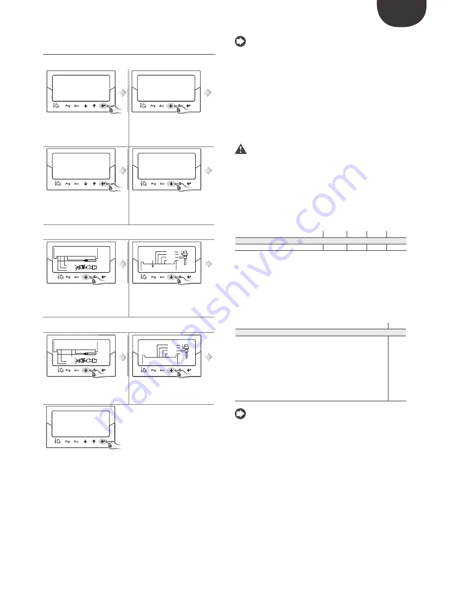
After having fitted the display:
Configuration 1/5
A
Network address
198
Configuration 1/5
A
Network address
198
1.
the first parameter is displayed:
network address;
2.
press Enter to move to the value
of the parameter
3.
press UP/DOWN to modify the
value
Configuration 1/5
A
Network address
1
Configuration 2/5
A
REFRIGERANT
R404A
Valve
Carel ExV
4.
press Enter to confirm the value
5.
press UP/DOWN to move to the
next parameter, refrigerant for driver
A, indicated by the letter at the top
right;
6.
repeat steps 2, 3, 4, 5 to modify the values of the parameters for driver A:
refrigerant, valve, pressure probe S1, main control;
TxRx
GND
DI1
S4
S3
S2
S1
GND
DI2
VREF
white
black
green
TEMP S2
PRESS S1
A
G
G0
VBA
T
CO
M
A
NO
A
1
3
2
4
yellow
white
brown
green
A
7.
check that the probe electrical
connections are correct for driver A;
8.
check that the electrical
connections are correct for valve A;
then set the same parameters for
driver B (see step 6);
9.
set the values of the parameters for driver B: refrigerant, valve B, pressure
probe S3, main control;
TxRx
GND
DI1
S4
S3
S2
S1
GND
DI2
VREF
white
black
green
TEMP S4
PRESS S3
B
COMB
NOB
1
3
2
4
yellow
white
brown
green
B
10. check that the probe electrical
connections are correct for driver B;
11. check that the electrical
connections are correct for valve B;
Configuration
End configuration?
YES
NO
12.
if the configuration is correct exit
the procedure, otherwise choose
NO and return to step 2.
At the end of the configuration procedure the controller activates the valve
motor error recognition procedure, displaying “INIT” on the display. See
paragraph 9.5. To simplify commissioning and avoid possible malfunctions,
the controller will not start until the following have been configured for each
driver:
4.
network address (common parameter);
5.
refrigerant;
6.
valve;
7.
pressure probe;
8.
type of main control, that is, the type of unit the superheat control is
applied to.
Note:
•
to exit the guided commissioning procedure press the DOWN button
repeatedly and finally confirm that configuration has been completed. The
guided procedure CANNOT be ended by pressing Esc;
•
if the configuration procedure ends with a configuration error, access
Service parameter programming mode and modify the value of the
parameter in question;
•
if the valve and/or the pressure probe used are not available in the list, select
any model and end the procedure. Then the controller will be enabled for
control, and it will be possible to enter Manufacturer programming mode
and set the corresponding parameters manually. Below are the parameters
for driver A and driver B to be set during the commissioning procedure.
These parameters have the same description for both driver A and driver
B, the user can recognise which parameter is being set by the letter A/B
shown at the top right of the display
.
Important:
for 24 Vdc power supply, at the end of the guided
commissioning procedure, to start control set “Power supply mode”
parameter=1, otherwise the valves remain in the closed position. See
paragraph 6.1.
N
etwork address
The network address assigns to the controller an address for the serial
connection to a supervisory system via RS485, and to a pCO controller via
pLAN, tLAN, RS485/Modbus®. This parameter is common to both drivers A
and B.
Parameter/description
Def.
Min.
Max.
UOM
CONFIGURATION
Network address
198
1
207
-
Tab. 4.a
For network connection of the RS485/Modbus® models the communication
speed also needs to be set, in bits per second, using the parameter “Network
settings”. See paragraph 6.2.
R
efrigerant
The type of refrigerant is essential for calculating the superheat. In addition, it
is used to calculate the evaporation and condensing temperature based on
the reading of the pressure probe.
Parameter/description
Def.
CONFIGURATION
Refrigerant
0 = user definer
1= R22
2= R134a
3= R404A 4= R407C
5= R410A
6= R507A
7= R290 8= R600
9= R600a
10= R717
11= R744
12= R728
13= R1270
14= R417A
15= R422D
16= R413A
17= R422A 18= R423A 19= R407A 20= R427A
21= R245FA 22= R407F
23=R32 24=HTR01
25=
HTR02
26=R23
27 = R1234yf 28 = R1234ze 29 = R455A 30 = R170
31 = R442A 32 = R447A
33 = R448A
34 = R449A 35 = R450A
36 = R452A 37 = R508B
38 = R452B
39 = R513A 40 = R454B
41 = R458A
R404A
Tab. 4.b
Note:
•
for CO
2
cascade systems, at the end of the commissioning procedure also
set the auxiliary refrigerant. See the following paragraph Appendix 2;
•
if the refrigerant is not among those available for the “Refrigerant”
parameter:
1.
set any refrigerant (e.g. leave the default, R404A);
2.
select the model of valve, the pressure probe S1, the type of main
control and end the commissioning procedure;
3.
enter programming mode and set the type of refrigerant: custom, and
the parameters “Dew a…f high” and “Bubble a…f low” that define the
refrigerant;
4.
start control, for example by closing the digital input contact to enable
operation.
Содержание EVD Evolution Twin
Страница 2: ......
Страница 4: ......
Страница 6: ......
Страница 66: ...ENG EVD Evolution TWIN 0300006EN rel 2 6 31 01 2019 66 Note...
Страница 67: ......


