background image

SRS-12H MANUAL 

Chapter 3: Operation 


15

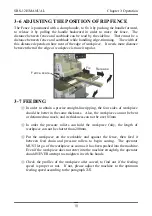
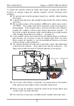
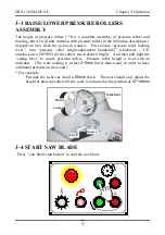
Rais e

Lower

Lock

R elease

Indicator

3-3 RAISE/LOWER PRESSURE ROLLERS 
ASSEMBLY  

The height of pressure rollers ( *It is a complete assembly of pressure rollers and 
housing, but we will only mention with pressure rollers in the following description. ) 
depends on how thick the to-be-cut wood is.    First release “pressure roller locking 
lever”, turn “pressure roller height-adjustment handwheel” (clockwise - UP, 
anticlockwise- DOWN) till the rollers reach desired height.    And then pull tight the 
“clamp lever” to secure pressure rollers.  Pressure roller height is read with an 
indicator.    (The scale reading is in fact 

2~3mm 

lower than wood, in order to have 

additional pressure on the wood.)


* For example


Presume the to-be-cut wood is 

50mm

 thick.    The user should only adjust the 

height of pressure rollers till the scale is indicated at the position of 

47~48mm. 


3-4 START SAW BLADE 

  Press “ saw blade start button” to start the saw blade 
 

Содержание C12RSH

Страница 1: ...ensure you have your serial number available when contacting us for parts or service Cantek America Inc 1 888 982 2683 Parts sales cantekamerica com Service service cantekamerica com C12RSH Straight L...

Страница 2: ...HP Volt Hz Saw arbor 1 7 5 10 15 Feed 1 2 Belt specifications 7 5 10 HP 5 pcs Triangular belt A 52 50Hz A 58 60Hz Saw motor 15 HP 3 pcs Triangular belt 3V 530 50Hz 3V 600 60Hz variable speed 1 pcs rib...

Страница 3: ...sional repair or maintenance contact your local dealer geving him the following information Model number Serial number Date of purchase Precise details of the fault or problem Your dealer can provide...

Страница 4: ...ON APPARATUS 11 CHAPTER 3 OPERATION 12 3 1 INSTALLING AND REMOVING BLADE 12 3 2 CHECKING SAFETY DEVICES 14 3 3 RAISE LOWER PRESSURE ROLLER ASSEMBLY15 3 4 START SAW BLADE 15 3 5 START FEED CHAIN 16 3 6...

Страница 5: ......

Страница 6: ...meter 200 300 mm 8 12 Saw blade bore 25 4 mm Feed motor 2 HP Feed speed Variable speed 17 40 M min 5 Step speed 18 22 28 34 42 M min Number of holding rollers 8 pcs Dust hole diameter 100 mm Work tabl...

Страница 7: ...motor by means of V belts There are 3 choices on saw motor 7 5HP 10HP or 15HP depending on work requirement VARIABLE FEEDING SPEEDS The feeding speed can be adjusted variably at any speed between 17 4...

Страница 8: ...brication system ensures a permanent oil film between feed chain and guide track If the oil in tank is below the safety level the warning lamp will light up and the feed chain will stop running automa...

Страница 9: ...SRS 12H MANUAL Chapter 1 Introduction 4 1 3 LOCATION OF PARTS...

Страница 10: ...adjustment Hand wheel 9 Control panel 10 Saw arbor height adjustment hand wheel 11 Anti kickback finger operation handle 12 First row of upper anti kickback fingers 13 Fence clamp handle 14 Rip fence...

Страница 11: ...roduction 6 Control panel 1 Emergent STOP button 2 Sawblade START button 3 Sawblade STOP button 4 Power indicator 5 Feed chain insufficeient lubrication indicator 6 Feed chain START button 7 Feed chai...

Страница 12: ...SRS 12H MANUAL Chapter 1 Introduction 7 Machine size...

Страница 13: ...any sign of having been hit after opening the package If either of the above situations has been happened please contact the local dealer immediately Let the qualified technicians manage this matter 2...

Страница 14: ...o re tighten the foundation screws 2 4 POWER CONNECTION The power source should be connected by a qualified electrician All wirings must conform to international safety guidelines choose a most suitab...

Страница 15: ...r clockwise direction If not the operator must shut off the power supply immediately Exchange any two of cables and rewire the machine then start the saw arbor again The green lamp of sawblade START b...

Страница 16: ...1 2 6 CONNECTION OF DUST COLLECTION APPARATUS The dust collection outlet is 100mm which can connect with one flexible tube of caliber 4 inches The air speed has to be higher than 25m sec and the air c...

Страница 17: ...the special offset wrench in anticlockwise Then you can take off the lock washer in order to install remove saw blade 2 Before install saw blade the user has to make sure the diameter of saw blade is...

Страница 18: ...the sawblade teeth refer to the above picture 4 Installed the saw blade and put the lock washer back Then fix the hex bolt of saw blade with the wrenches we mentioned at the step 1 5 When saw blade is...

Страница 19: ...Close the saw arbor cover check and make certain all limit switches and the lateral safety guard are at the functional position And the top anti kickback fingers hang down in a row and point to the d...

Страница 20: ...urn pressure roller height adjustment handwheel clockwise UP anticlockwise DOWN till the rollers reach desired height And then pull tight the clamp lever to secure pressure rollers Pressure roller hei...

Страница 21: ...stem Variable speed option and 5 Step speed 1 Variable Speed Option How to adjust Turn the speed shift knob until the indicator points the speed you desired Decrease the speed by turning clockwise Inc...

Страница 22: ...otor cover then use a 19mm Open end wrench to adjust the 2 Hex bolts turning clockwise to release as pointed in the following picture Refer to the FEED SPEED CHANGING TABLE which is attached on the in...

Страница 23: ...ping the four sides of workpiece should be better in the same thickness Also the workpiece can not be bent or deformed too much and its thickness can not be over 85mm In order the pressure rollers can...

Страница 24: ...19 CHAPTER 4 SAFETY PRECAUTIONS There are some precautions and warnings to be stuck on the machine The operator must read them carefully before handling this machine and remind himself all the time to...

Страница 25: ...accident the pressure rollers must be adjusted to a proper position while changing the thickness of workpiece see page 13 As the sawdust will be stuck between the anti kickback fingers to influence t...

Страница 26: ...st be sure that the surface of groove is clean dry and dust free completely 2 Use 3M Scotch Grip 847 Rubber Gasket Adhesive to fix the new rubber insert 3 Brush of flow a thin coat of adhesive evenly...

Страница 27: ...on the feed chain Otherwise the margin of wood will be fallen because of pressed with pressure rollers and then influence the accuracy of workpiece It is dangrous to rip a workpiece which is warped in...

Страница 28: ...turns Always use the circular sawbalde which is suitable for woodcutting The blades should be checked regularly and make sure it is no bluntness crack and accumulation of sawdust on it Make certain t...

Страница 29: ...wdust on the feed chain will suck lubricant If the feed chain slide on guide track without enough lubricant it will cause serious wear on feed chain The operator must clean up the sawdust on every cha...

Страница 30: ...d or required Every day Check the oil level in the feed chain lubrication tank each day before operation and fill it up if necessary If the lubricant insufficient indicator lights up during operation...

Страница 31: ...grease gun should be cleaned completely at first to avoid any impurity object following the grease into the bearings and damage them Please check the position of oil nozzles on the machine as the pict...

Страница 32: ...est using the grease offered by the machine manufacturer or its agents Add SAE 90 lubricating oil to the oil filler point until it rises above the oil level window 5 3 ADJUST AND REPLACE SAW ARBOR BEL...

Страница 33: ...ey the operator needs to remove the cover and inspect the belt immediately If the belt shows signs of wear or appears to be split it should be replaced according to the following procedures 1 Start th...

Страница 34: ...d of periodic lubrication to output a certain volume of oil every 5 minutes Mechanical lubricator The volume of oil output follows the feed speed by means of a crank coupling The faster of feed speed...

Страница 35: ...oil supply is getting less Before we ship the machine we have adjusted each adjust screw at the oil supply 0 45 c c per shot the total quantity of 2 outlets is 0 9c c 3 Use 2 spanners to fix the NUT...

Страница 36: ...cate the Screw Nut and Slide Way of roller housing When clean up and lubricate these parts be sure to adjust the Roller Housing to the highest and lowest position 2 Repeat to raise and lower the Rolle...

Страница 37: ......
Отзывы: