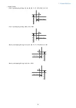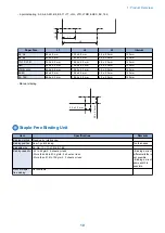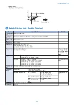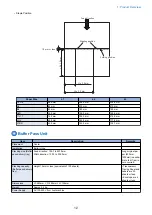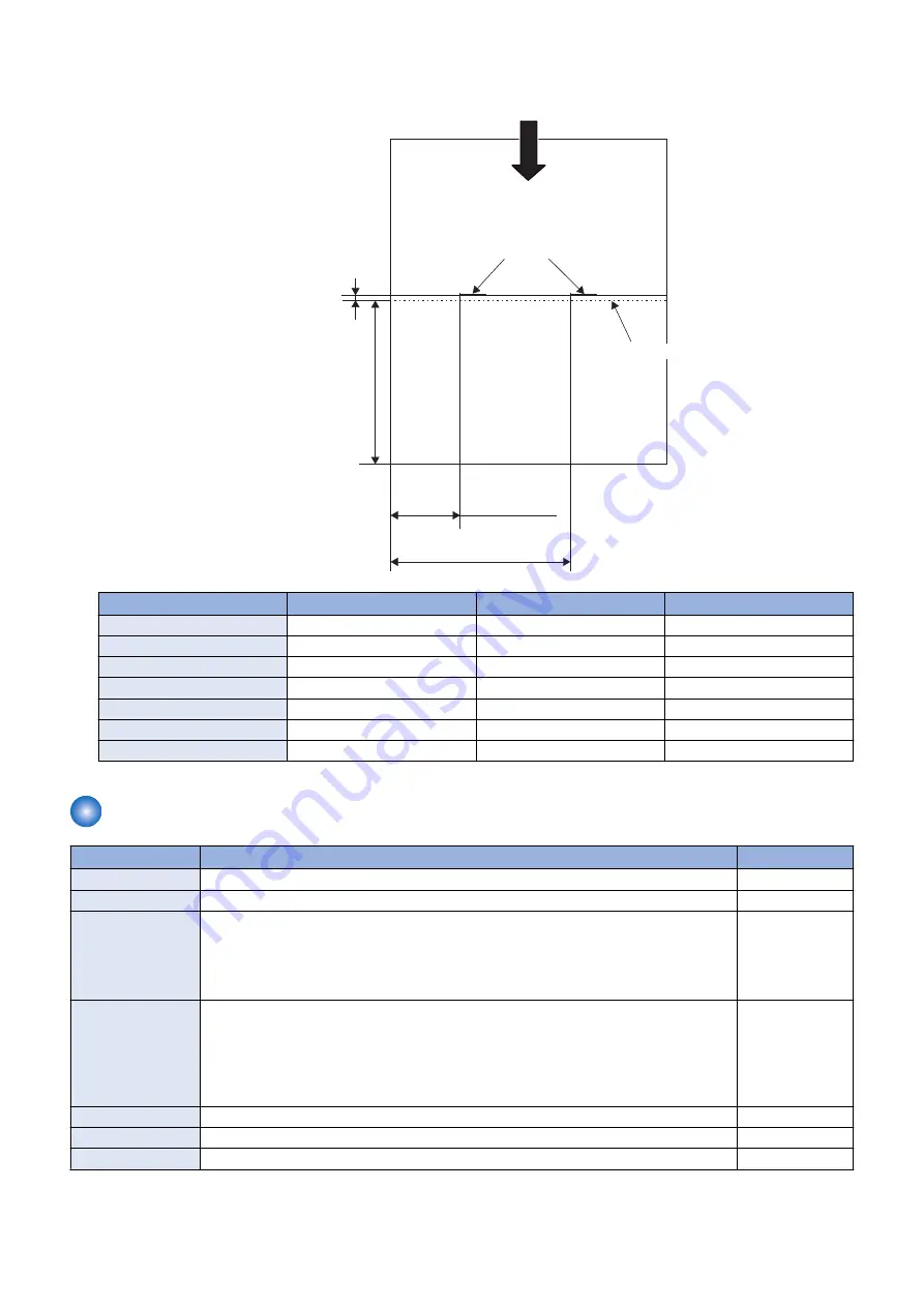
• Staple Position
L2 ± 2.0 mm
L
3
±
1
.0
mm
L1 ± 2.0 mm
Stapling position
Feed direction
1.0 mm or less
Folding position
Paper Size
L1
L2
L3
12"×18"
86.9 mm
206.9 mm
228.6 mm
A3
83 mm
203 mm
210 mm
B4
63 mm
183 mm
182 mm
A4R
39.5 mm
159.5 mm
148.5 mm
11×17
74.2 mm
194.2 mm
215.9 mm
LGL
42.5 mm
162.5 mm
177.8 mm
LTRR
42.5 mm
162.5 mm
139.7 mm
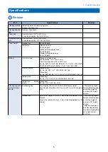
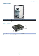
Buffer Pass Unit
Item
Description
Remarks
Placement
Center
Installation
Build-in type
Stacking size (Buffer
pass delivery tray)
Feed direction: 139.7 to 457.0mm
Width direction: 100.0 to 305.0mm
Long original pa-
per (630mm,
1200mm) is availa-
ble to fed if jam is
not occurred.
Stacking capacity
(Buffer pass delivery
tray)
Height 15mm or less (equivalent of 100 sheets)
• Transparency,
Tracing Paper and
Labels are 20
sheets or less.
• Envelope are 4
sheets or less.
Dimensions
W: 480mm × D: 485mm × H: 155mm
Weight
Approx 5.4 kg
Power Supply
AC100-240V from host machine
1. Product Overview
12
Содержание Staple Finisher-AA1
Страница 1: ...Revision 4 0 Staple Finisher AA1 Booklet Finisher AA1 Service Manual ...
Страница 12: ...Product Overview 1 Features 5 Specifications 6 Names of Parts 14 Optional Configuration 20 ...
Страница 83: ...Periodical Service 3 Periodic Servicing Tasks 76 ...
Страница 87: ...3 Remove the 2 Connectors 1 2x 1 4 Parts Replacement and Cleaning 79 ...
Страница 89: ...Main Units Parts 4 5 6 7 8 1 2 3 4 Parts Replacement and Cleaning 81 ...
Страница 128: ...4x 1 2 2 3 3 2x 4 Parts Replacement and Cleaning 120 ...
Страница 150: ...Adjustment 5 Overview 143 Basic Adjustment 148 Adjustments When Replacing Parts 173 Other 184 ...
Страница 178: ...A B Feed Direction Stapling Position Fixing Screw A B Stitcher Unit Fixing Screw Fixing Screw Mark 5 Adjustment 170 ...
Страница 184: ... Adjsting Phase Angle of the Paddle Unit 1 Put off the belt 1 1 2 Lower the swing roller till its end 5 Adjustment 176 ...
Страница 193: ...Troubleshooting 6 Making Initial Checks 186 Processing Tray Area 187 Saddle Stitcher Area 188 ...
Страница 204: ...4 5 6 7 8 9 7 Installation 196 ...
Страница 205: ...10 7 Installation 197 ...
Страница 210: ...11 NOTE Keep the parts as illustration above Installation of Buffer Pass Unit 1 7 Installation 202 ...
Страница 223: ...2 3 2x 7 Installation 215 ...
Страница 224: ...APPENDICES Service Tools 217 General Circuit Diagram 218 ...

