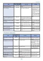
Items
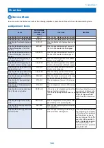
Service Mode
(SORTER > AD-
JUST)
Use case
Remarks
Adjusting the delivery speed at the
staple mode
STP-SPD
When the paper stacking at staple mode or
staple-free binding mode is misalignment.
- When the value is decreased,
the productivity is decreased.
- When the buffer operation is
performed, delivery speed
does not change. (The buffer
operation is the operation to
deliver the stacking paper on
the processing tray). The
ON/OFF of buffer operation is
set by BUFF-SW.
Adjusting the delivery speed of the
escape tray
ESC1-SPD
When the paper stacking to the escape tray
is misalignment.
Adjusting the binding pressure at
the staple-free binding mode
FR-ST-PS
Upon user's request (When changing the
binding pressure).
The life of staple-free binding
unit becomes shorter when in-
creasing the setting value.
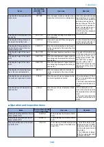
Adjusting the binding position for
the front/rear direction at the sta-
plefree binding mode
FR-STP-Y
When the binding position in front/rear di-
rection is displaced at the staple-free bind-
ing mode.
Adjusting the height of the return
belt 1
RBLT-PRS
When the paper alignment position is irreg-
ular.
The height of Return Belt dur-
ing the paper alignment on the
processing tray is the total of
setting values of RBLT-PS2
and PBLT-PS3, so adjust
again the setting value of
RBLT-PS2 if necessary when
changing the setting value of
RBLT-PS3.
Adjusting the height of the return
belt 2
RBLT-PS2
When the misalignment of paper stack oc-
curs during alignment operation on the pro-
cessing tray.
Adjusting the height of the return
belt 3
RBLT-PS3
When the misalignment of paper stack oc-
curs during alignment operation on the pro-
cessing tray.
Adjusting the front/rear staple posi-
tion at the manual staple mode
MSTP-2P
When the staple position for front/rear di-
rection is displaced at the manual staple
mode.
Adjusting the punch hole position in
the horizontal registration direction
PNCH-Y
When the punch hole is misaligned in the
horizontal registration direction.
- When the setting of "PUN-Y-
SW" is 0, the adjustable range
is from -3 to 15.
- This mode is available when
the puncher unit has been in-
stalled.
Adjusting the punch hole position in
feed direction
PNCH-X
When the punch hole is displaced in feed
direction
- When setting the punch
mode to the precision priority,
this adjustment cannot be exe-
cuted.
- This mode is available when
the puncher unit has been in-
stalled.
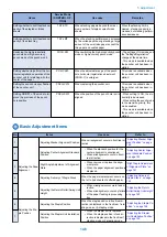
■ Operation and inspection items
Items
Service Mode (SORT-
ER > FUNCTION)
Use case
Remarks
Reading the backup data from the fin-
isher controller PCB
FIN-BK-R
When replacing the finisher controller
PCB.
Writing the backup data from the fin-
isher controller PCB
FIN-BK-W
When replacing the finisher controller
PCB.
Clearing the RAM data of the finisher
controller PCB
FIN-CON
When clearing the RAM data (excluding
the counter values) of the finisher con-
troller PCB
- Output the service mode
setting values by P-PRINT
before execution. After exe-
cution, enter necessary set-
ting values.
- The RAM data is cleared
after the main power switch
is turned OFF/ON.
5. Adjustment
144
Содержание Staple Finisher-AA1
Страница 1: ...Revision 4 0 Staple Finisher AA1 Booklet Finisher AA1 Service Manual ...
Страница 12: ...Product Overview 1 Features 5 Specifications 6 Names of Parts 14 Optional Configuration 20 ...
Страница 83: ...Periodical Service 3 Periodic Servicing Tasks 76 ...
Страница 87: ...3 Remove the 2 Connectors 1 2x 1 4 Parts Replacement and Cleaning 79 ...
Страница 89: ...Main Units Parts 4 5 6 7 8 1 2 3 4 Parts Replacement and Cleaning 81 ...
Страница 128: ...4x 1 2 2 3 3 2x 4 Parts Replacement and Cleaning 120 ...
Страница 150: ...Adjustment 5 Overview 143 Basic Adjustment 148 Adjustments When Replacing Parts 173 Other 184 ...
Страница 178: ...A B Feed Direction Stapling Position Fixing Screw A B Stitcher Unit Fixing Screw Fixing Screw Mark 5 Adjustment 170 ...
Страница 184: ... Adjsting Phase Angle of the Paddle Unit 1 Put off the belt 1 1 2 Lower the swing roller till its end 5 Adjustment 176 ...
Страница 193: ...Troubleshooting 6 Making Initial Checks 186 Processing Tray Area 187 Saddle Stitcher Area 188 ...
Страница 204: ...4 5 6 7 8 9 7 Installation 196 ...
Страница 205: ...10 7 Installation 197 ...
Страница 210: ...11 NOTE Keep the parts as illustration above Installation of Buffer Pass Unit 1 7 Installation 202 ...
Страница 223: ...2 3 2x 7 Installation 215 ...
Страница 224: ...APPENDICES Service Tools 217 General Circuit Diagram 218 ...

