


Chapter 7
7-19
setting range: -100 (lighter) to +100 (darker)
COPIER> ADJUST> V-CONT> DE-OFST)
(adjusting VDC for copier)
COPIER> ADJUST> V-CONT> DE-OFS-P)
(adjusting VDC for printer)
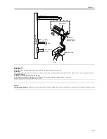
Enter the value indicated on the service label if you have initialized the RAM on the DC control PCB.
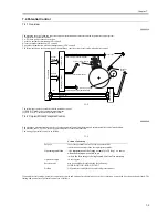
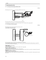
7.7.3 Detecting the Toner Level and Controlling Toner Supply
0009-4120
The following shows the components associated with the toner supply control system:
F-7-24
[1] Toner bottle
[2] Hopper assembly
[3] Toner stirring plate
[4] Toner feedscrew
[5] Toner feed pipe
[6] Developing assembly
M9: Hopper stirring motor
M10: Toner supply motor
TS1: Toner level sensor
TS2: Inside hopper toner level sensor
DC-CON: DC controller (components used to detect level of remaining toner)
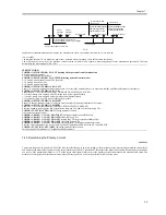
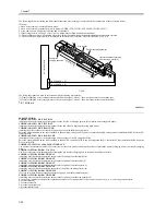
Toner Supply Sequence
The toner inside the developing assembly is monitored by the developing assembly toner sensor (TS1); when the toner inside the developing assembly
falls below a specific level, the developing assembly toner level signal goes '0' so that the DC controller PCB recognizes it.
If the DC controller PCB detects the developing assembly toner level signal for 0.3 sec or more, it generates the hopper motor drive signal so that the
hopper assembly will start supplying toner.
When the toner inside the developing assembly reaches a specific level and, as a result, the developing assembly toner level signal remains '1' for 0.7 sec
or more, the hopper supply motor stops.
When the toner inside the hopper drops below a specific level, the hopper toner level detection signal goes '0'. If the signal remains '0' when the toner supply
motor has been turned on and off 20 times after the detection of the signal state by the DC controller, the machine issues a message of bottle exchange.
Total rotating time reaches 60 seconds after the toner sensor in the developing assembly senses no toner, the machine issues a method of exchanging bottles
and stops the ongoing printing operation.
When the toner bottle is replaced, the hopper supply motor and the stirring motor are turned on, and the developing assembly inside toner level detection
signal goes '1', the machine resets the message of bottle exchange and resumes printing.
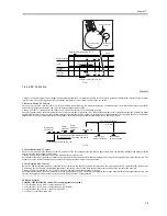
F-7-25
M10
M9
DC-CON
J103B
HOP_TONER_SENSOR[2]
J103A
DEV_TONER_SENSOR[4]
HOP_BOTTLE_ON[3]
HOP_BOTTLE
_ON[1]
TS2
[1]
[2]
[3]
[4]
[6]
TS1
Toner supply sequence start
Toner supply
Hopper supply motor
(M10)
Developing assembly
toner sensor (TS1)
Hopper toner sensor
(TS2)
Supply
Supply
If 120 sec or more,
'020-0000' is indicated
total activation (ON) time of hopper
stirring motor reaching 60 sec, message of
method of exchanging bottles -> print suspension.
1 cycle (5 sec max.)
toner supply motor driven for 20 cycles,
message of exchanging bottles.
Содержание iR6570 series
Страница 1: ...Mar 29 2005 Service Manual iR6570 5570 Series...
Страница 2: ......
Страница 6: ......
Страница 26: ...Contents...
Страница 27: ...Chapter 1 Introduction...
Страница 28: ......
Страница 30: ......
Страница 55: ...Chapter 2 Installation...
Страница 56: ......
Страница 58: ...Contents 2 9 3 Mounting the Cassette Heater 2 34...
Страница 98: ......
Страница 99: ...Chapter 3 Basic Operation...
Страница 100: ......
Страница 102: ......
Страница 110: ......
Страница 111: ...Chapter 4 Main Controller...
Страница 112: ......
Страница 114: ......
Страница 135: ...Chapter 5 Original Exposure System...
Страница 136: ......
Страница 181: ...Chapter 6 Laser Exposure...
Страница 182: ......
Страница 184: ......
Страница 192: ......
Страница 193: ...Chapter 7 Image Formation...
Страница 194: ......
Страница 198: ......
Страница 259: ...Chapter 8 Pickup Feeding System...
Страница 260: ......
Страница 299: ...Chapter 8 8 35 F 8 51 PS36 M19 M14 Reversing flapper Outside delivery roller Point of reversal PS37...
Страница 349: ...Chapter 8 8 85 F 8 290 1 Feeding roller 2 Separation roller 3 Pressure lever 4 Pressure spring 1 2 A B 3 4...
Страница 350: ......
Страница 351: ...Chapter 9 Fixing System...
Страница 352: ......
Страница 401: ...Chapter 10 External and Controls...
Страница 402: ......
Страница 406: ......
Страница 448: ......
Страница 449: ...Chapter 11 MEAP...
Страница 450: ......
Страница 452: ......
Страница 455: ...Chapter 12 Maintenance and Inspection...
Страница 456: ......
Страница 458: ......
Страница 468: ......
Страница 469: ...Chapter 13 Standards and Adjustments...
Страница 470: ......
Страница 505: ...Chapter 14 Correcting Faulty Images...
Страница 506: ......
Страница 508: ......
Страница 537: ...Chapter 15 Self Diagnosis...
Страница 538: ......
Страница 540: ......
Страница 565: ...Chapter 16 Service Mode...
Страница 566: ......
Страница 568: ......
Страница 633: ...Chapter 17 Upgrading...
Страница 634: ......
Страница 636: ......
Страница 641: ...Chapter 17 17 5 F 17 4 HDD Boot ROM Flash ROM System Software...
Страница 646: ...Chapter 17 17 10 F 17 11 8 Click START F 17 12...
Страница 659: ...Chapter 17 17 23 F 17 32 2 Click Start F 17 33 3 When the downloading session has ended click OK...
Страница 661: ...Chapter 17 17 25 F 17 35 2 Click Start F 17 36 3 When the downloading session has ended click OK...
Страница 663: ...Chapter 17 17 27 F 17 38 2 Click Start F 17 39 3 When the downloading session has ended click OK...
Страница 668: ...Chapter 17 17 32 F 17 46 2 Click Start F 17 47 3 When the downloading session has ended click OK...
Страница 675: ...Chapter 17 17 39 F 17 59 2 Select the data to download F 17 60 3 Click Start...
Страница 677: ...Chapter 18 Service Tools...
Страница 678: ......
Страница 679: ...Contents Contents 18 1 Service Tools 18 1 18 1 1 List of Special Tools 18 1 18 1 2 List of Solvents Oils 18 2...
Страница 680: ......
Страница 683: ...Mar 29 2005...
Страница 684: ......