


Chapter 6
6-5
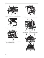
F-6-4
MEMO:
1. The laser power is adjusted automatically when the laser unit is replaced.
2. When the manual feed tray is used as the source of paper, the write operation starts when the registration paper sensor (PS29) detects paper.
SERVICE MODE:
DISPLAY> DPOT> LLMT-P
indicates the laser power voltage control value for printer (PDL) imaging.
DISPLAY> DPOT> LLMT
indicates the laser power voltage control value for copier imaging.
DISPLAY> DPOT> LPOWER-P
indicates the result of potential control for the laser intensity used during printer (PDL) imaging.
DISPLAY> DPOT> LPOWER-C
indicates the result of potential control for the laser intensity used during copier imaging.
DISPLAY> MISC> LPOWER
indicates the laser intensity in real time.
ADJUST> LASER> PVE-OFST
used to adjust the laser incident point.
FUNCTION> LASER> POWER
used to turn on laser light.
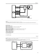
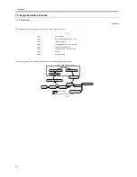
6.3.2.2 APC Control
0009-5252
The machine executes APC control so that the laser light will remain at a constant level by adjusting the output of the laser diode mounted on the laser
driver.
The control mechanism takes place on the DC control PCB.
The DC controller sends the laser control signal (CTL0=0, CTL1=1) to the laser driver IC on the laser driver PCB.
In response, the laser driver IC sets APC mode, and forces the laser diode (LD) to emit light.
While all this is under way, the laser driver IC monitors the laser diode (LD) by means of a photo diode (PD), and adjusts the output of the laser diode unit
so that the intensity is at a specific level.
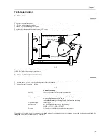
F-6-5
J117
J113
J121
LD(+) [1]
5.5V
LD(-) [1]
GND
LWRPD [4]
Laser driver PCB
DC controller
PCB
J102
[6]
J101
Laser block
Laser
Intensity
monitor [5]
Laser
drive
circuit
EEPROM
3
2
1
B2
9
8
7
5
4
3
2
1
6
1
2
3
5
6
7
8
4
4
3
2
1
GND
LZ-LDPSEL[7]
GND
Laser write
start sensor (PS28)
Laser unit
GND
GND
CTL1[3]
CTL0[2]
[1]
Laser Driver
5V
PD
LD
CTL1
CTL0
DC-CON
J101
J121
Содержание iR6570 series
Страница 1: ...Mar 29 2005 Service Manual iR6570 5570 Series...
Страница 2: ......
Страница 6: ......
Страница 26: ...Contents...
Страница 27: ...Chapter 1 Introduction...
Страница 28: ......
Страница 30: ......
Страница 55: ...Chapter 2 Installation...
Страница 56: ......
Страница 58: ...Contents 2 9 3 Mounting the Cassette Heater 2 34...
Страница 98: ......
Страница 99: ...Chapter 3 Basic Operation...
Страница 100: ......
Страница 102: ......
Страница 110: ......
Страница 111: ...Chapter 4 Main Controller...
Страница 112: ......
Страница 114: ......
Страница 135: ...Chapter 5 Original Exposure System...
Страница 136: ......
Страница 181: ...Chapter 6 Laser Exposure...
Страница 182: ......
Страница 184: ......
Страница 192: ......
Страница 193: ...Chapter 7 Image Formation...
Страница 194: ......
Страница 198: ......
Страница 259: ...Chapter 8 Pickup Feeding System...
Страница 260: ......
Страница 299: ...Chapter 8 8 35 F 8 51 PS36 M19 M14 Reversing flapper Outside delivery roller Point of reversal PS37...
Страница 349: ...Chapter 8 8 85 F 8 290 1 Feeding roller 2 Separation roller 3 Pressure lever 4 Pressure spring 1 2 A B 3 4...
Страница 350: ......
Страница 351: ...Chapter 9 Fixing System...
Страница 352: ......
Страница 401: ...Chapter 10 External and Controls...
Страница 402: ......
Страница 406: ......
Страница 448: ......
Страница 449: ...Chapter 11 MEAP...
Страница 450: ......
Страница 452: ......
Страница 455: ...Chapter 12 Maintenance and Inspection...
Страница 456: ......
Страница 458: ......
Страница 468: ......
Страница 469: ...Chapter 13 Standards and Adjustments...
Страница 470: ......
Страница 505: ...Chapter 14 Correcting Faulty Images...
Страница 506: ......
Страница 508: ......
Страница 537: ...Chapter 15 Self Diagnosis...
Страница 538: ......
Страница 540: ......
Страница 565: ...Chapter 16 Service Mode...
Страница 566: ......
Страница 568: ......
Страница 633: ...Chapter 17 Upgrading...
Страница 634: ......
Страница 636: ......
Страница 641: ...Chapter 17 17 5 F 17 4 HDD Boot ROM Flash ROM System Software...
Страница 646: ...Chapter 17 17 10 F 17 11 8 Click START F 17 12...
Страница 659: ...Chapter 17 17 23 F 17 32 2 Click Start F 17 33 3 When the downloading session has ended click OK...
Страница 661: ...Chapter 17 17 25 F 17 35 2 Click Start F 17 36 3 When the downloading session has ended click OK...
Страница 663: ...Chapter 17 17 27 F 17 38 2 Click Start F 17 39 3 When the downloading session has ended click OK...
Страница 668: ...Chapter 17 17 32 F 17 46 2 Click Start F 17 47 3 When the downloading session has ended click OK...
Страница 675: ...Chapter 17 17 39 F 17 59 2 Select the data to download F 17 60 3 Click Start...
Страница 677: ...Chapter 18 Service Tools...
Страница 678: ......
Страница 679: ...Contents Contents 18 1 Service Tools 18 1 18 1 1 List of Special Tools 18 1 18 1 2 List of Solvents Oils 18 2...
Страница 680: ......
Страница 683: ...Mar 29 2005...
Страница 684: ......