CHAPTER 2 STANDARDS AND ADJUSTMENTS
2-46
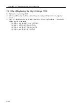
7.6 When Replacing the High-Voltage PCB
1) Replace the high-voltage PCB.
2) After assembling the machine, connect the power plug, and turn on the main power
switch.
3) Enter the values recorded on the label attached to the new high-voltage PCB in the fol-
lowing service mode items:
COPIER>ADJUST>DEVELOP>HVT-DE
COPIER>ADJUST>HV-TR>HVT-TR
COPIER>ADJUST>HV-TR>H-PRE-TR
COPIER>ADJUST>HV-SP>HVT-SP
Содержание IR5000 - iR B/W Laser
Страница 72: ...CHAPTER 2 STANDARDS AND ADJUSTMENTS 2 52 Blank Page ...
Страница 104: ......
Страница 121: ...CHAPTER 4 SERVICE MODE 4 17 ALARM 1 Indicates alarm data ALRM 1 1 1 READY BODY 00 DF 00 SORTER ww xx yy zz F04 201 04 ...
Страница 123: ...CHAPTER 4 SERVICE MODE 4 19 2 2 FEEDER FEEDSIZE Indicates the size of an original detected by the ADF FEEDER DISPLAY ...
Страница 224: ......
Страница 234: ......

