CHAPTER 4 SERVICE MODE
4-22
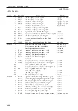
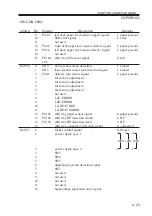
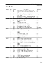
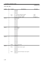
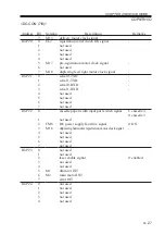
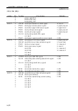
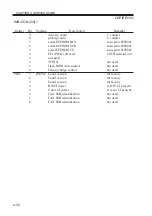
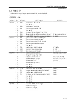
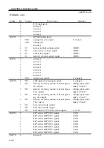
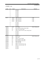
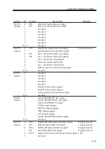
COPIER>I/O
<DC-CON (2/8)>
Address
IO-P04
IO-P05
Bit
3
4
5
6
7
8
9
10
11
12
13
14
15
0
1
2
3
4
5
6
7
8
9
10
11
12
13
14
15
0
1
2
3
4
5
6
7
8
Notation
PS10
PS12
PS17
PS18
SV1
SV1
CL2
PS5
PS9
PS3
SW2
PS15
PS16
SV2
SV2
TH2
TH1
RL1
FM1
FM2
FM6
FM3
FM7
FM4
FM8
FM5
PS47
Description
left deck lifter sensor signal
left deck limit sensor signal
cassette 3 lifter sensor signal
cassette 4 lifter sensor signal
cassette 4 universal detection
cassette 4 length detection signal 0
cassette 4 length detection signal 1
registration roller clutch drive signal
right deck open/closed detection sensor signal
left deck open/closed sensor signal
right cover open/closed detection signal
not used
front cover open/closed detection signal
duplexing unit detection signal
fixing/feeding unit detection signal
hard disk unit detection signal
cassette 3 open/closed sensor signal
cassette 4 open/closed sensor signal
cassette 3 size detection signal 0
cassette 3 size detection signal 1
not used
fixing sub thermistor error detection signal 1
fixing main thermistor error detection signal
E001 error hard detection signal
fixing sub thermistor error detection signal 2
main relay OFF detection signal
main SSR error signal
sub SSR error signal
DC controller switch signal
separation feeder fan stop detection signal
primary charging cooling fan stop detection signal
DC power supply fan stop detection signal
heat discharge fan stop detection signal
hard disk fan stop detection signal
controller cooling fan stop detection signal
duplexing feed fan stop detection signal
de-curling fan stop detection signal
right deck paper level sensor (upper) signal
Remarks
1: paper present
1: limit
1: paper present
1: paper present
0: universal
1: ON
1: closed
1: closed
1: closed
0: closed
0: connected
0: connected
1: absent
1: closed
1: closed
1: error
1: error
1: error
1: error
1: error
1: error
1: new
1: stop
1: stop
1: stop
1: stop
1: stop
1: stop
1: stop
1: stop
1: paper present
Содержание IR5000 - iR B/W Laser
Страница 72: ...CHAPTER 2 STANDARDS AND ADJUSTMENTS 2 52 Blank Page ...
Страница 104: ......
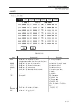
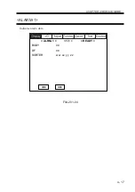
Страница 121: ...CHAPTER 4 SERVICE MODE 4 17 ALARM 1 Indicates alarm data ALRM 1 1 1 READY BODY 00 DF 00 SORTER ww xx yy zz F04 201 04 ...
Страница 123: ...CHAPTER 4 SERVICE MODE 4 19 2 2 FEEDER FEEDSIZE Indicates the size of an original detected by the ADF FEEDER DISPLAY ...
Страница 224: ......
Страница 234: ......

