CHAPTER 2 STANDARDS AND ADJUSTMENTS
2-11
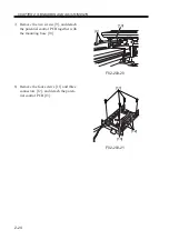
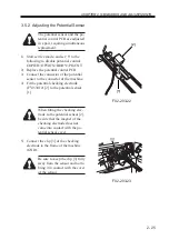
2) Insert the pins of the mirror positioning
tool (front [2]/rear [3]) into each of the
holes [1]: No. 1 mirror base, No. 2 mir-
ror base, and rail. The position of the
No. 2 mirror base is adjusted by sliding
the cable fixing plate to the front and
the rear.
F02-202-02
F02-202-03
3) Secure the end of the cable so far tem-
porarily fixed to the hook of the reader
frame using a spring.
4) Fully tighten the screw on the cable fix-
ing plate.
5) Fully tighten the cable metal fixing on
the No. 1 mirror base.
6) Detach the mirror positioning tool.
7) Reverse steps 1) through 6) for mount-
ing.
[2]
[1]
[3]
[1]
Содержание IR5000 - iR B/W Laser
Страница 72: ...CHAPTER 2 STANDARDS AND ADJUSTMENTS 2 52 Blank Page ...
Страница 104: ......
Страница 121: ...CHAPTER 4 SERVICE MODE 4 17 ALARM 1 Indicates alarm data ALRM 1 1 1 READY BODY 00 DF 00 SORTER ww xx yy zz F04 201 04 ...
Страница 123: ...CHAPTER 4 SERVICE MODE 4 19 2 2 FEEDER FEEDSIZE Indicates the size of an original detected by the ADF FEEDER DISPLAY ...
Страница 224: ......
Страница 234: ......


