CHAPTER 2 STANDARDS AND ADJUSTMENTS
2-20
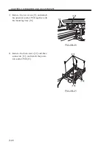
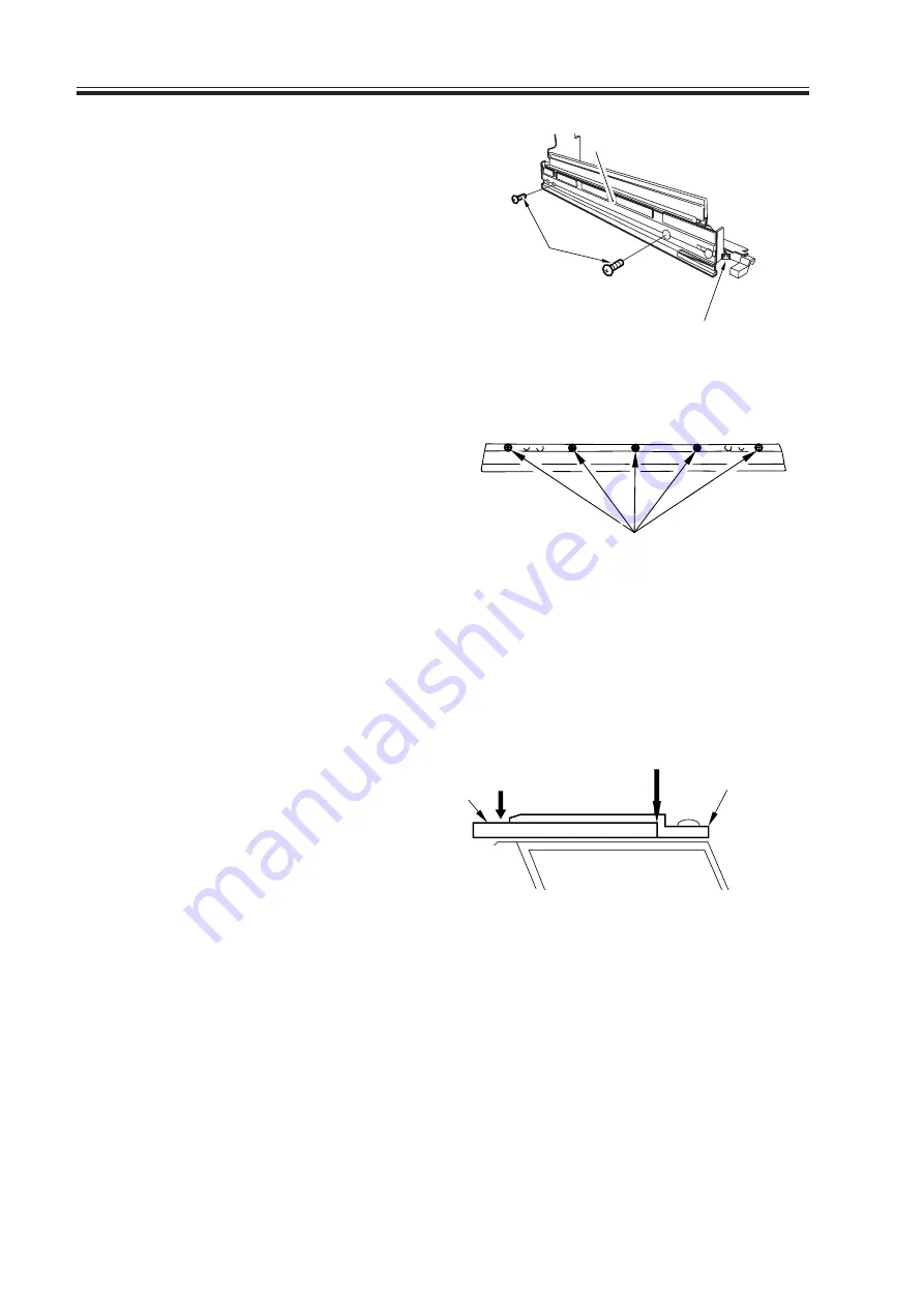
6) Disconnect the connector [6], and re-
move the two screws [7]; then, detach
the pre-exposure LED assembly [8].
F02-203-11
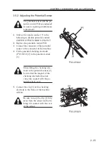
7) Loosen the five mounting screws [9],
and detach the blade support plate from
the cleaning blade.
F02-203-12
3.3.2 Mounting the Cleaning Blade
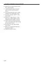
When mounting the cleaning blade, be sure that the side with the marking [1] will be the
face.
1) Push in the cleaning blade [2] until it
butts slightly again the rear.
F02-203-13
[6]
[7]
[8]
[9]
No gap
Blade retaining
plate
[2]
[1]
Содержание IR5000 - iR B/W Laser
Страница 72: ...CHAPTER 2 STANDARDS AND ADJUSTMENTS 2 52 Blank Page ...
Страница 104: ......
Страница 121: ...CHAPTER 4 SERVICE MODE 4 17 ALARM 1 Indicates alarm data ALRM 1 1 1 READY BODY 00 DF 00 SORTER ww xx yy zz F04 201 04 ...
Страница 123: ...CHAPTER 4 SERVICE MODE 4 19 2 2 FEEDER FEEDSIZE Indicates the size of an original detected by the ADF FEEDER DISPLAY ...
Страница 224: ......
Страница 234: ......


