CHAPTER 2 STANDARDS AND ADJUSTMENTS
2-14
5) Cut the twisted charging wire (excess)
with nippers.
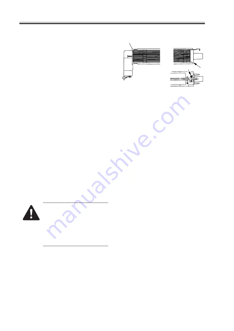
6) Hook the loop on stud A.
7) After routing the wire for 31 runs, lead
it through section B, and give it a half
turn; then, put it between the washer
and the motor unit, and wind it once
around the mounting screw (clockwise),
and secure it in place with a mounting
screw.
F02-203-03
8) Cut the excess of the charging wire with
nippers.
9) Tighten the mounting screw loosened in
step 3).
Keep tightening until the tension of the
grid wire is even.
Be sure to pay attention to avoid defor-
mation (slack) of the charging assembly
(as by tightening the mounting screw
found on the front of the left/right
shielding plate early).
10) Tighten the mounting screws loosened
in steps 1) and 2).
11) Wipe the grid wire with lint-free paper
moistened with alcohol.
1. Check to make sure that the
grid wire is free of bending
and twisting.
2. Be sure that the runs are laid
at equal intervals (i.e., the
wire is in the groove of the
block).
Stud A
Screw
B
Содержание IR5000 - iR B/W Laser
Страница 72: ...CHAPTER 2 STANDARDS AND ADJUSTMENTS 2 52 Blank Page ...
Страница 104: ......
Страница 121: ...CHAPTER 4 SERVICE MODE 4 17 ALARM 1 Indicates alarm data ALRM 1 1 1 READY BODY 00 DF 00 SORTER ww xx yy zz F04 201 04 ...
Страница 123: ...CHAPTER 4 SERVICE MODE 4 19 2 2 FEEDER FEEDSIZE Indicates the size of an original detected by the ADF FEEDER DISPLAY ...
Страница 224: ......
Страница 234: ......


