CHAPTER 4 SERVICE MODE
4-23
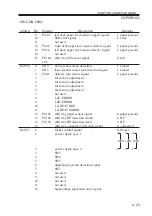
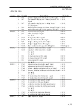
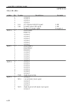
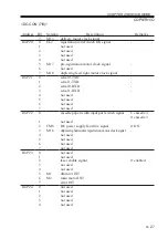
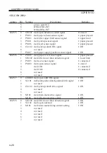
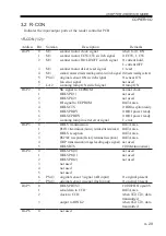
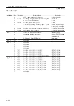
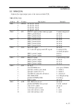
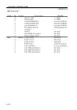
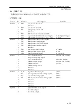
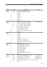
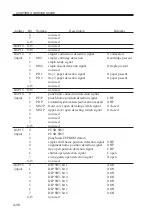
COPIER>I/O
<DC-CON (3/8)>
0
100V
0
1
120V
0
0
230V
1
Address
IO-P06
IO-P07
Bit
9
10
11
12
13
14
15
0
1
2
3
4
5
6
7
8
9
10
11
12
13
14
15
0
1
2
3
4
5
6
7
8
9
10
11
12
Notation
PS49
PS48
PS50
PS104/
105
M19
M15
PS46
PS103
PS104
PS105
Description
left deck paper level sensor (upper) signal
SSR error signal
not used
right deck paper level sensor (lower) signal
left deck paper level sensor (lower ) signal
not used
shift tray full sensor signal
fixing motor clock detection
laser scanner motor lock detection signal
delivery jam sensor signal
for factory adjustment
for factory adjustment
for factory adjustment
for factory adjustment
not used
LZC-ERROR
LZD-ERROR
LZ-HEAT RDY
LZ-HEAT ERROR
shift tray paper sensor signal
shift tray HP detection (front)
shift tray HP detection (rear)
shift tray connection detection signal
flicker control signal
power supply spec 1
power supply spec 2
SW3
SW4
SW5
duplexing feed fan detection signal
SW7
not used
not used
not used
not used
high-voltage separation error signal
Remarks
1: paper present
1: error
1: paper present
1: paper present
0: full
1: locked
1: locked
1: paper present
0: paper present
1: HP
1: HP
0: connected
0: flicker
Содержание IR5000 - iR B/W Laser
Страница 72: ...CHAPTER 2 STANDARDS AND ADJUSTMENTS 2 52 Blank Page ...
Страница 104: ......
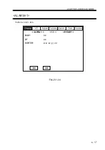
Страница 121: ...CHAPTER 4 SERVICE MODE 4 17 ALARM 1 Indicates alarm data ALRM 1 1 1 READY BODY 00 DF 00 SORTER ww xx yy zz F04 201 04 ...
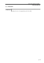
Страница 123: ...CHAPTER 4 SERVICE MODE 4 19 2 2 FEEDER FEEDSIZE Indicates the size of an original detected by the ADF FEEDER DISPLAY ...
Страница 224: ......
Страница 234: ......

