background image

2-2

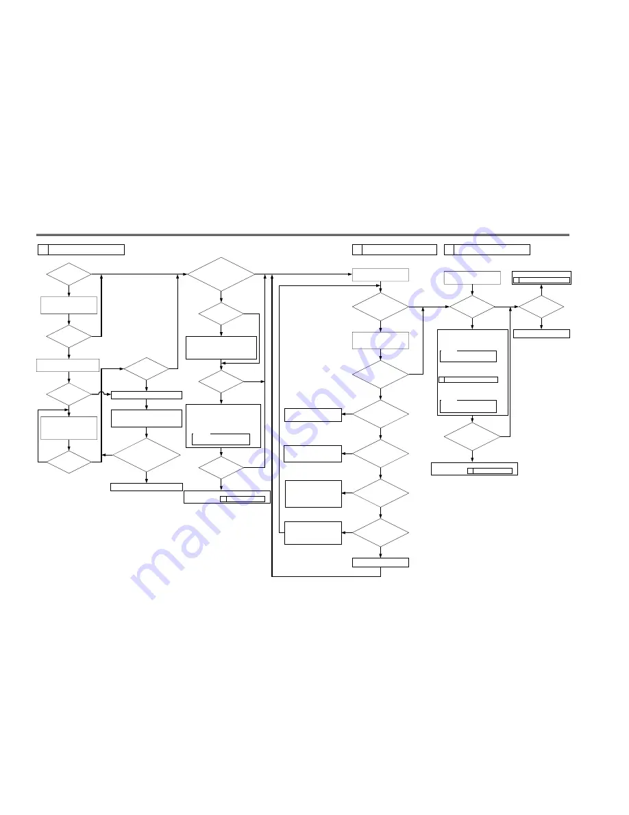
CHAPTER 2 IMAGE ADJUSTMENT BASIC PROCEDURE

YES

NO

NO

NO

NO

NO

NO

NO

NO

NO

NO

Is there a 

vertical line in 

the image?

YES

YES

YES

YES

YES

YES

YES

YES

YES

Is there a 

vertical line in 

the image?

Is there ea 

vertical line in the 

image?

Is the setting of the 

following in service mode 485 

µ

A: 

DISPLAY>HV-STS>

PRIMARY?

Replace the composite power supply PCB.

Is there a 

vertical line on the 

surface of the 

sleeve?

NO

NO

YES

NO

NO

NO

NO

NO

NO

YES

YES

YES

YES

Is there a 

line on the surface 

of the sleeve?

Clean the following:
[1] Laser mirror
[2] No. 1 mirror

Generate 10 test prints of the 
following in service mode: 
COPIER>TEST>PG.
TYPE6 (solid black)

Check the surface of the 
developing sleeve by the naked eye.

Replace the drum unit.

Execute the following service mode: 
COPIER>FUNCTION>DPC>D-GAMMA.
 (initialization)

Is the image of TYPE6 

(solid black) on test prints correct in 

density and free 

of fuzziness?

Is the image fuzzy?

Is the image 

density appropriate?

Is the image 

density appropriate?

Check the following, 
and correct any fault:
[1] Feeding assembly for locking
[2] Transfer charging roller electrode

Adjust the setting of the following in 
service mode: 
COPIER>ADJUST>DEVELOP>DE-DC.
• If the image is light, decrease the setting.
• If the image is dark, increase the setting.

Caution:
Be sure to vary the setting in 
equal amounts.

Check the image density by 
generating test prints (TYPE5).

Is there an 

appreciable difference 
in density between left 

and right of the 

image?

YES

Clean the following:
[1] Laser mirror:
[2] No. 1 mirror

Are both rear and 

front of the pre-exposure 

lamp ON?

Is there a difference 

in density between left and 

right of the image?

YES

YES

NO

YES

Is the developing 

assembly securely locked 

in place?

Is the coating of toner 

on the developing 

sleeve uneven?

Replace the pre-exposure 
lamp unit.

Lock it securely. If the locking 
mechanism has a fault, replace it.

Generate 10 test prints (TYPE6);
 then, if the coating of toner on 
the developing sleeve is uneven, 
replace the developing assembly.

Is the 

feeding assembly 

(transfer charging roller) locked 

securely in place?

Lock the feeding assembly 
(transfer charging roller) 
securely; if the locking 
mechanism is faulty, replace the 
transfer charging roller unit.            

Replace the laser scanner unit.

Check the image density by 
generating test prints (TYPE4).

Are the printouts 

foggy?

Is the image density 

of the tense prints (TYPE6) 

appropriate?

Is there a fault in 

the copy image?

2   Checking the Scanner Side.

End.

1   Making Initial Checks.

Increase the setting of the following in 
service mode: 
COPIER>ADJUST>DEVELOP>DE-DC.

  Caution:
 Be sure to vary the setting in 
  equal amounts.

However, if the setting has already been 
changed under

3   Checking the Printer Side (1/3),

decrease the following in service mode: 
COPIER>ADJUST>HV-PRI>P-DC.

  Caution:


  Be sure to vary the setting in 
  equal amounts.

3

Checking the Printer Side (1/3)

4 Checking the Printer Side (2/3)

5

Checking the Printer Side (3/3)

1   Making Initial Checks.

Replace the developing assembly, and make image 

adjustments under

Replace the developing assembly, and make image 

adjustments under 

Go to

Содержание iR2200 Series

Страница 1: ...iR2200 iR2800 iR3300 REVISION 0 SERVICE HANDBOOK FY8 23BD 000 MAY 2001 COPYRIGHT 2001 CANON INC CANON iR2200 iR2800 iR3300 REV 0 MAY 2001 PRINTED IN JAPAN IMPRIME AU JAPON...

Страница 2: ...of this manual over a long or short period Canon will issue a new edition of this manual The following paragraph does not apply to any countries where such provisions are inconsistent with local law T...

Страница 3: ...cking the Scanner Side 2 1 3 Checking the Printer Side 1 3 2 2 4 Checking the Printer Side 2 3 2 2 5 Checking the Printer Side 3 3 2 2 CHAPTER 3 STANDARDS AND ADJUSTMENTS 1 Image Adjustments 3 1 1 1 S...

Страница 4: ...troller PCB 3 12 3 Image Formation System 3 13 3 1 Positioning the Developing Assem bly Magnetic Seal 3 13 3 2 Mounting the Developing Assembly Blade 3 13 3 3 Removing the Paper Lint 3 14 3 4 Cleaning...

Страница 5: ...1 2 The DC power is absent 4 29 4 2 Printer Unit 4 30 4 2 1 Pickup fails 4 30 4 2 2 The lifter fails to move up pickup from the cassette 4 31 4 2 3 The vertical path roller fails to rotate 4 32 4 2 4...

Страница 6: ...4 46 6 1 Introduction 4 46 6 1 1 Guide to the List 4 46 6 1 2 Checking the Photointerrupters 4 47 6 2 E201 reader unit printer unit 4 48 6 2 1 Clutches 4 48 6 2 2 Solenoids Switches 4 48 6 2 3 Motors...

Страница 7: ...s 7 14 1 4 2 Connection 7 15 1 4 3 Preparing BOOT ROM 7 15 1 4 4 After Downloading 7 19 1 5 Formatting the HDD 7 20 1 5 1 Making Connections 7 20 1 5 2 Starting Formatting 7 20 1 5 3 Points to Note Wh...

Страница 8: ...2 1 Systems A 15 3 Cassette Feeding Unit W1 A 16 3 1 Systems A 16 4 Inner 2way Tray A1 A 17 4 1 Type A 17 5 Envelope Feeder Attachment B1 A 18 5 1 Systems A 18 5 2 Envelopes A 19 5 3 Guaranteed Image...

Страница 9: ...the user s The estimates are subject to change depending on the conditions of the site of installation or how the machine is used 1 1 Reader Unit The reader unit does not have parts that require perio...

Страница 10: ...emarks 1 Transfer roller FF6 0104 1 240 000 2 Transfer static eliminator FF5 7246 1 240 000 3 Developing cylinder FG6 5714 1 480 000 4 Fixing cleaning roller FG6 5709 1 150 000 5 Pre exposure lamp FG5...

Страница 11: ...1 240 000 Actual prints made 4 Separation roller FB2 7777 020 1 240 000 Actual prints made T01 204 01 2 5 Cassette Feeding Unit As of March 2001 No Part name Part No Q ty Life prints Remarks 1 Pickup...

Страница 12: ...ion and back for soiling The margin must meet the following standards Leading edge 2 5 1 5 mm Left edge 2 5 1 5 mm Right edge 0 5 mm or more Trailing edge 2 5 1 1 1 7 mm smaller than B4 2 5 2 0 mm 3 5...

Страница 13: ...by the government concerned 2 Do not dispose of waste toner into fire to avoid explosion 10 Make test copies 11 Make sample copies 12 Check the operation of the leakage breaker While the power switch...

Страница 14: ...4 1 Reader Unit Clean Replace Lubricate Adjust Inspect T01 401 01 Part Scanner cable Scanner rail Copyboard glass No 1 through No 3 mirror Original illumination reflecting plate Original size sensor L...

Страница 15: ...er lint Transfer guide Developing member Base developing as sembly Waste toner case Unit Laser opti cal unit Pickup feeding as sembly Developing assembly Waste toner collection assembly Upon in stalla...

Страница 16: ...No 1 through No 3 mirrors Cleaning blower brush Reflecting shade Cleaning blower brush Copyboard glass Cleaning Original size sensor Cleaning blower brush Scanner rail Lubricating Scanner cable Check...

Страница 17: ...ding edge or left right edges of prints If soiling is noted clean also the transfer guide and the static eliminator at the same time as the bottom of the developing assembly 6 1 Cleaning the Bottom of...

Страница 18: ......

Страница 19: ...Is the copy density normal Vary the setting in service mode COPIER ADJUST DENS DENS ADJ If the image is dark decrease the setting If the image is light increase the setting Is the copy image density...

Страница 20: ...d right of the image YES Clean the following 1 Laser mirror 2 No 1 mirror Are both rear and front of the pre exposure lamp ON Is there a difference in density between left and right of the image YES Y...

Страница 21: ...non image width of a print made in Direct must be as follows F03 101 01 Image Leading Edge Margin F03 101 02 Left Right Image Margin F03 101 04 Left Non Image Width when the DADF H1 picks up an origi...

Страница 22: ...idth are as indicated Each cassette Manual feed tray Duplex feeding unit Side paper deck If not as indicated adjust the image position in the following order 1 Adjusting the left right image margin re...

Страница 23: ...form the adjustments that follow COPIER FUNCTION MISC P CI ADJ Y C2 ADJ Y C3 ADJ Y C4 ADJ Y 1 Remove the cassette 2 Remove the two screws 1 and detach the horizontal registration base assem bly 2 F03...

Страница 24: ...3 03 1 3 3 Adjusting the Registration for the Deck Try the following service mode first if not corrected perform the adjustments that follow COPIER FUNCTION MISC P DK ADJ Y 1 Slide out the compartment...

Страница 25: ...djust the non image width in service mode so that it is as indicated COPIER ADJUST ADJ XY ADJ Y when the DADF H1 picks up an original in stream readig mode F03 105 01 Edge of paper Decreasing the REGI...

Страница 26: ...After Replacing the Scanning Lamp Run CCD auto adjustment in Service Mode This updates the CCD adjustment data Print out a new service label 1 CCD Auto Adjust COPIER FUNCTION CCD CCD ADJ 2 CCD Adjustm...

Страница 27: ...orarily 3 Fit the spring 5 to apply tension to the belt 3 4 Check to make sure that the belt 3 is vertical F03 202 01 5 While taking care not to hold the scan ning lamp 1 or the reflecting shade 2 mov...

Страница 28: ...at it will not turn idly 4 runs inside 5 runs outside then tape it in place At this time check to make sure that the cable fixing is on the inside 3 Engage the cable with each pulley and temporarily f...

Страница 29: ...ition of the No 1 No 2 Mirror Base 1 Set the pins of the mirror positioning tool as indicated For the Front F marking initial FY9 3009 set for the machine F03 204 01 For the Rear R marking initial FY9...

Страница 30: ...and froth movement of the cable fixing plate Front Side F marking F03 204 03 Rear Side R marking F03 204 04 3 Fix the end of the cable which is tem porarily secured on the hook of the reader frame in...

Страница 31: ...gainst the vertical horizontal size plate 2 If not done properly the shadow of the size plate will appear on images made in enlargement mode After mounting make an 800 en largement copy to check There...

Страница 32: ...2 7 Points to Note When Replacing the CCD Unit Run CCD auto adjustment and End gain control position auto adjustment in Service Mode This updates the CCD ad justment data Print out a service label wit...

Страница 33: ...301 01 3 2 Mounting the Developing Assembly Blade The blade 1 and the blade base 2 of the blade base unit are ad justed to a high accuracy at the factory Do not disassemble the unit If you happen to h...

Страница 34: ...S 3 14 3 3 Removing the Paper Lint 1 Open the front cover 2 Remove the paper lint cleaning cover 1 by inserting a flat blade screwdriver F03 303 01 3 Slide out the paper lint cleaning lever 1 and move...

Страница 35: ...the waste toner case 3 F03 304 01 3 Dispose of the waste toner collecting inside the waste toner case 4 Clean both inside and the outside of the waste toner case 1 area A indicated by shading with al...

Страница 36: ...Check to see if the feeding assembly is locked in place 2 Match the arrow of the gear of the lock ing cam unit 1 against the middle of the gear 3 of the fixing drive unit e i where the rear 4 of the g...

Страница 37: ...ront cover so that gap A between the front cover 1 and the front upper cover 2 is 3 1 mm F03 501 02 If you operate the deck without matching the position of the pa per level indicator and the deck lif...

Страница 38: ...felt F03 502 01 5 3 Adjusting the Position of the Support Member If the compartment cannot be opened closed smoothly and the position of the sup port roller must be adjusted perform the following 1 R...

Страница 39: ...ear of the machine F03 504 01 Body Rear collar gold colored When mounting the deck pickup roller 2 to the rear of the machine be sure that the marking 4 on the collar 3 and the marking 5 on the side o...

Страница 40: ...y be attached to the pickup feeding roller shaft in either orientation F03 506 01 5 7 Adjusting the Deck Separation Roller Pressure If double feeding or pickup failure occurs when the deck is used as...

Страница 41: ...ckup roller releasing solenoid 1 from the support plate keep note of the position of the sole noid with reference to the two fixing screws 2 on the solenoid Or mark the position of the solenoid on the...

Страница 42: ...right cover of the machine 4 Loosen the two fixing screws 2 of the side member 1 5 With the side member in contact with the floor tighten the fixing screws At this time refer to the index so that the...

Страница 43: ...D ADJUSTMENTS 3 23 6 Cassette Feeding Unit W1 6 1 Mounting the Pedestal Main Motor 1 When mounting the pedestal main mo tor be sure to tighten the screws in the order indicated in the figure 1 through...

Страница 44: ...DL and YOUKEI 4 Use the red painted spring for C5 and B5 7 2 Replacing the Spring 7 2 1 Replacing the Spring 1 Remove the two mounting screws 1 each and detach the side guide plate 2 front rear and th...

Страница 45: ...o make sure that the spring is firmly on the bottom plate F03 702 03 7 3 Changing the Size 7 3 1 Changing the Size 1 Match the lifter 1 and the side guide plate 2 against the size positioning line of...

Страница 46: ...side guide rear is symmetrically opposite F03 703 02 2 Register the specifications of the enve lope using register envelope offered as part of common settings 3 Check to make sure that envelopes are...

Страница 47: ...e level 7 The source of power must provide power night and day Check the sight against the above requirements 1 2 Checking the Originals Check to find out if the symptom is caused by the originals use...

Страница 48: ...can result 1 6 Checking the Paper 1 Check to see if the paper used is of a recommended type Advise the user that paper not of a recommended type may fail to bring about expected results 2 Check to see...

Страница 49: ...inside the machine causing various problems Memo 1 Condensation in the optical system glass mirror lens can cause dark images 2 Condensation in the charging system can cause leakage 3 Condensation on...

Страница 50: ...CHAPTER 4 TROUBLESHOOTING IMAGE FAULTS MALFUNCTIONS 4 4 Blank Page...

Страница 51: ......

Страница 52: ...opy has black lines feeding direction fuzzy thick 2 Thecopyistoolight bothhalftoneandsolidblack 3 The copy is too light entire copy appreciably 9 The copy has black lines feeding direction fine 15 The...

Страница 53: ...e Is the text too light YES Execute AE adjustment Decrease the setting of the following in service mode COPIER ADJUST AE AE TBL Developing assembly 3 Are the block members of the developing assembly i...

Страница 54: ...roller 3 Is the feeding unit locked in place correctly NO Check the transfer charging roller pressure spring 4 Is there electrical leakage around the electrode of the feeding unit YES Check the electr...

Страница 55: ...sembly fitted securely Check to see if the develop ing block members are in firm contact with the photosensitive drum NO Fit the developing assembly correctly Toner level detection assembly developmen...

Страница 56: ...for a lose hex screw Feeding unit tranfer charging roller 5 Is the feeding unit locked in place correctly Is the transfer roller in contact with the photosensitive drum whet the feed ing unit is lock...

Страница 57: ...there foreign matter in the transfer guide assembly or the transfer charging roller and is there leakage NO Try fresh paper or paper of a different type Development fault 11 Is the developing assembly...

Страница 58: ...eration NO 1 Replace the pre exposure lamp unit 2 Replace the DC controller PCB Developing assembly 4 Is the coating of toner on the developing cylinder even NO 1 Clean the tip of the blade of the dev...

Страница 59: ...power supply PCB Developing assembly 4 Is the developing cylinder insulated from the GND of the machine Turn off the main power switch and disconnect the connector J130 of the composite power supply...

Страница 60: ...and lenses Is the problem corrected YES End Developing assembly 3 Is the coating of toner on the developing cylinder even NO 1 Check the edge of the blade of the developing assembly 2 Dry wipe the su...

Страница 61: ...the problem corrected YES End Photosensitive drum 3 Is there a scratch or a black line in the peripheral direction of the sur face of the photosensitive drum Be sure to wipe the black line on the sur...

Страница 62: ...static eliminator Developing assembly 4 Is the coating of toner on the developing cylinder even NO Check the edge of the developing assembly If the developing as sembly is without toner see the descr...

Страница 63: ...urface of the developing cylinder If a scratch is found on the surface of the developing cylinder re place the developing cylinder Drum unit 3 Does the problem occur at intervals of about 94 mm YES Cl...

Страница 64: ...te about 50 to 650V NO Check the transfer guide bias connector Clean the transfer guide Clean the bottom of the developing assembly Developing assembly Registration roller Drum cleaner 4 Does the prob...

Страница 65: ...ilm unit Fixing heater 4 Does the heater operate NO See The fixing heater fails to operate Fixing lower roller pressure 5 Is the lower roller pressure nip width as indicated NO Replace the fixing asse...

Страница 66: ...ckup feeding or separation roller of the cassette in question reached the end of its life YES Check the roller if worn replace it REGIST 4 Execute the following in service mode ADJUST FEED ADJ REGIST...

Страница 67: ...e slowly by hand Does it move smoothly NO Clean the surface of the scanner rail with alcohol thereafter apply a small amount of silicone oil Drum drive assembly Photosensitive drum 3 Does the problem...

Страница 68: ...r PCB Drum unit 3 Does the problem occur at intervals of 94 mm YES Replace the drum unit Wiring 4 Is the wiring between the scanning lamp the inverter PCB and the reader assembly NO Correct the wiring...

Страница 69: ...osition of the No 1 mirror an the No 2 mirror Developing bias 4 Are the connection and the electrical continuity of the high voltage for the developing bias normal The resistance of the cable for the...

Страница 70: ...unting condition 5 Is leakage noted on the transfer charging roller YES Check the transfer charging roller Transfer high voltage cord 6 Is the connection of the transfer high voltage cord normal Is th...

Страница 71: ...Is the wiring between the CCD PCB and the reader controller PCB nor mal NO Correct the wiring Laser scanner unit Drum unit 11 Try replacing the drum unit Is the problem corrected NO Check the laser s...

Страница 72: ...d electri cal continuity from J130 7 of the composite power supply PCB to the pri mary charring roller normal The resistance of the high voltage cord for primary charging is 10 k NO Correct the fault...

Страница 73: ...age nor mal YES End Drum unit 2 Set the following to 1 OPTION BODY PRIAC SW Then make copies of the NA 3 Chart Is the copy image normal YES End NO Replace the drum unit 3 24 The copy has a black line...

Страница 74: ...r outlet 2 Is the rated AC voltage present at the power outlet 3 Has the leakage breaker gone ON 2 Switch PCB Wiring Connector Is the resistance 0 when the switch is turned on and when it is turned of...

Страница 75: ...wn YES Remove the cause of the fuse and replace the fuse 3 Main power supply PCB Composite power supply PCB Is the output voltage of each power supply PCB normal a Main Power Supply PCB b Composite Po...

Страница 76: ...aration roller Execute pickup operation Does the roller rotate YES The movement of paper is faulty because of wear on the pickup feeding separate roller Replace the roller 5 Pickup drive assembly Is t...

Страница 77: ...cent lever Is any of the gear faulty damaged YES Replace it 4 Lifter drive assembly Is the gear of the lifter drive assembly damaged or subject to foreign matter Is the drive belt faulty YES Replace t...

Страница 78: ...FUNCTION PART CHK CL i e CL ON Is the clutch control signal present at J302A 4 of the DC controller PCB YES Replace the pickup PCB NO Replace the DC controller PCB 4 2 4 The registration roller fails...

Страница 79: ...CL i e CL ON Is the clutch drive signal present between J302B 7 and 8 of the DC controller PCB J302B 7 24 V J302B 8 MLT_CL YES Check the wiring if normal replace the clutch NO Replace the DC controll...

Страница 80: ...drum unit and the drive assembly of the drum drive unit If a fault is discovered correct the fault or replace the unit 4 2 8 The pre exposure lamp fails to go ON 1 Pre exposure lamp LAMP2 DC controlle...

Страница 81: ...from the scanner rail Remove any object that comes into contact with the scanner Use alcohol for cleaning thereafter apply a small amount of silicone oil FY9 6010 If the inverter PCB is not positioned...

Страница 82: ...wring and connect the connectors securely 2 Inverter PCB Is E220 indicated YES Replace the inverter PCB 3 Scanning lamp Reader controller PCB Execute the following in service mode COPIER FUNCTION MIS...

Страница 83: ...Is the shorting con nector fitted to the connector J1060 of the main control card NO Fit the shorting connector YES The main controller PCB is faulty Replace the PCB 4 4 3 The Add Paper message fails...

Страница 84: ...ck the interval between J200 1 and J200 3 on the main power supply PCB for electrical continuity NO Replace the front cover switch 3 Main power supply PCB Is 24 V supplied by the main power supply PCB...

Страница 85: ...the deck pickup roller rotate YES If the roller is soiled clean it with alcohol If it is deformed be cause of wear replace it 4 Belt displacement Is the belt used to transmit drive to the deck pickup...

Страница 86: ...ring and the lever 4 Deck lifter motor M2D Does the deck lifter motor rotate YES Go to step 6 5 Deck open detecting switch SW1D Deck drive PCB Does the voltage between J7 1 24V OUT and J7 3 GND 24V IN...

Страница 87: ...according to location 1 Pickup assembly 2 Separation feeding assembly 3 Fixing delivery assembly duplex reversing assembly 4 Duplex feeding assembly The descriptions that follow are also grouped accor...

Страница 88: ...corrected YES Check the faulty cassette 4 Paper moist Is the paper curled or wavy or in any way different YES Replace the paper Advise the user on the correct method of storing paper 5 Paper non recom...

Страница 89: ...O Check the wiring if normal replace the sensor 5 Registration roller Feeding unit transfer charging roller Does the registration roller rotate NO Check the registration motor M9 YES Check to make sur...

Страница 90: ...gin 5 1 4 Duplex Feeding Assembly 1 Paper guide plate Is there foreign matter around the paper guide Or is it deformed YES Remove the foreign matter and correct the deformation 2 Duplex inlet paper se...

Страница 91: ...gh the feeding as sembly At this time is the paper wrinkled Or is it moving askew YES 1 Check the pickup assembly 2 Check the guide in front of the registration roller 3 Check the registration roller...

Страница 92: ...se in the general circuit diagrams enabling reference to the general circuit diagrams for wiring and signal descriptions For the general circuit diagrams see the Ap pendix 6 1 1 Guide to the List The...

Страница 93: ...creen b Open Closed Sensor Check the Service Mode screen while opening closing the cover unit in question c Position Sensor Presence Absence Sensor Move the unit in question by hand Try removing and t...

Страница 94: ...CHAPTER 4 TROUBLESHOOTING IMAGE FAULTS MALFUNCTIONS 4 48 6 2 E201 reader unit printer unit 6 2 1 Clutches 6 2 2 Solenoids and Switches F04 602 01 SL5 SL6 CL3 CL2 SW3 SW1 SW2 CL1 SL1...

Страница 95: ...7 Developing clutch 0 ON 1 OFF 6 2 2 Solenoids and Switches Reader Unit The reader unit does not have any solenoid or switch Printer Unit Electrical signal target Reference to general I O address Rema...

Страница 96: ...CHAPTER 4 TROUBLESHOOTING IMAGE FAULTS MALFUNCTIONS 4 50 6 2 3 Motors 1 2 F04 602 02 M1 M2 M3 M4 M5 M6 M9 M10 M400...

Страница 97: ...turn to origin IO P01 5 6 Default IO P04 6 Analog IO P06 0 0 new current mode Printer Unit 1 2 Electrical signal target Reference to general I O address Remarks Name circuit diagram I O indication M1...

Страница 98: ...CHAPTER 4 TROUBLESHOOTING IMAGE FAULTS MALFUNCTIONS 4 52 6 2 3 Motors 2 2 F04 602 02 M1 M2 M3 M4 M5 M6 M9 M10 M400...

Страница 99: ...nit 2 2 Electrical signal target Reference to general I O address Remarks Name circuit diagram I O indication M6 DC CON A3 8 N P005 0 to 7 Duplex motor M9 DC CON A3 14 M P002 5 Registration motor 1 OF...

Страница 100: ...CHAPTER 4 TROUBLESHOOTING IMAGE FAULTS MALFUNCTIONS 4 54 6 2 4 Fans F04 602 03 FM4 FM5 FM1 FM2 FM3...

Страница 101: ...o general I O address Remarks Name circuit diagram I O indication FM1 DC CON A3 18 N P004 0 2 Developing fan 1 ON 0 OFF P009 4 0 ON FM2 DC CON A3 18 J P004 1 3 Fixing fan 1 ON 0 OFF P009 5 0 ON FM3 MN...

Страница 102: ...CHAPTER 4 TROUBLESHOOTING IMAGE FAULTS MALFUNCTIONS 4 56 6 2 5 Sensors 1 3 F04 602 04 S5 S4 PS23 PS12 PS10 PS11 PS9 PS1 6 PS22 PS8 PS7 PS26 PS13 S2 PS15 PS17 PS18 PS16 PS400 PS401 S3 S1 VR1 SD1 BD...

Страница 103: ...to general I O address Remarks Name circuit diagram I O indication BD DC CON A3 13 K BD sensor PS1 DC CON A3 19 N P013 5 Cassette 1 paper sensor 0 present 1 absent paper PS2 DC CON A3 19 M P014 5 Cass...

Страница 104: ...CHAPTER 4 TROUBLESHOOTING IMAGE FAULTS MALFUNCTIONS 4 58 6 2 5 Sensors 2 3 F04 602 04 S5 S4 PS23 PS12 PS10 PS11 PS9 PS1 6 PS22 PS8 PS7 PS26 PS13 S2 PS15 PS17 PS18 PS16 PS400 PS401 S3 S1 VR1 SD1 BD...

Страница 105: ...DC CON A3 8 J P015 5 Fixing feeding sensor 0 present 1 absent paper PS15 DC CON A3 8 N P015 6 No 1 delivery sensor 1 present 0 absent paper PS16 DC CON A3 9 N P015 7 No 1 delivery full sensor 1 prese...

Страница 106: ...CHAPTER 4 TROUBLESHOOTING IMAGE FAULTS MALFUNCTIONS 4 60 6 2 5 Sensors 3 3 F04 602 04 S5 S4 PS23 PS12 PS10 PS11 PS9 PS1 6 PS22 PS8 PS7 PS26 PS13 S2 PS15 PS17 PS18 PS16 PS400 PS401 S3 S1 VR1 SD1 BD...

Страница 107: ...Electrical signal target Reference to general I O address Remarks Name circuit diagram I O indication S4 DC CON A3 17 J P013 0 to 4 Cassette 1 size sensor S5 DC CON A3 16 J P014 0 to 4 Cassette 2 siz...

Страница 108: ...CHAPTER 4 TROUBLESHOOTING IMAGE FAULTS MALFUNCTIONS 4 62 6 2 6 Lamps Heaters and Others F04 602 05 LAMP1 H5 H4 CB1 PLG1 LAMP2 H3 H1 H2 TP1 TH1 TH2...

Страница 109: ...Scanning lanp Printer Unit Electrical signal target Reference to general I O address Remarks Name circuit diagram I O indication CB1 MPWS A3 14 A Leakage breaker H1 MPWS A3 9 C Fixing main heater H2 M...

Страница 110: ...CHAPTER 4 TROUBLESHOOTING IMAGE FAULTS MALFUNCTIONS 4 64 6 2 7 PCBs F04 602 06 3 11 9 9 5 13 2 7 6 10 10 8 1 12 10 4 14...

Страница 111: ...wer supply PCB power 3 Controls the main power Switch PCB switch heater 4 Controls the printer unit DC controller PCB 5 Controls the pickup assembly Pickup PCB 6 Controls laser drive Laser driver PCB...

Страница 112: ...CHAPTER 4 TROUBLESHOOTING IMAGE FAULTS MALFUNCTIONS 4 66 6 3 Side Paper Deck L1 6 3 1 Clutches 6 3 2 Solenoids and Switches 6 3 3 Motors F04 603 01 M1D SL2D M2D SL1D LED100D CL2D CL1D SW2D SW1D SW100D...

Страница 113: ...dress Remarks Name circuit diagram I O indication SL1D DECK CON A5 10 A Deck pickup roller 0 ON 1 OFF releasing solenoid SL2D DECK CON A5 4 B Deck open solenoid 0 ON 1 OFF SW1D DECK CON A5 3 H Deck op...

Страница 114: ...CHAPTER 4 TROUBLESHOOTING IMAGE FAULTS MALFUNCTIONS 4 68 6 3 4 Sensors 6 3 5 PCBs F04 603 02 1 PS6D PS5D PS1D PS4D PS2D PS3D PS8D PS9D PS7D...

Страница 115: ...CK CON A5 12 A Deck paper absent sensor PS3D DECK CON A5 11 A Deck lifter upper limit sensor PS4D DECK CON A5 11 A Deck lifter position sensor PS5D DECK CON A5 3 C Deck set sensor PS6D DECK CON A5 10...

Страница 116: ...CHAPTER 4 TROUBLESHOOTING IMAGE FAULTS MALFUNCTIONS 4 70 6 4 2 Cassette Feeding Unit W1 6 4 1 Clutches 6 4 2 Solenoids and Switches 6 4 3 Motors F04 604 01 S1C S2C M1C M2C SL1C CL1C...

Страница 117: ...ectrical signal target Reference to general I O address Remarks Name circuit diagram I O indication SL1C PEDE FEED A6 11 F Pickup roller DOWN solenoid 0 ON 1 OFF S1C PEDE CON A6 7 A Cassette 3 size de...

Страница 118: ...CHAPTER 4 TROUBLESHOOTING IMAGE FAULTS MALFUNCTIONS 4 72 6 4 4 Sensors 6 4 5 PCBs F04 604 02 2 1 PS1C PS2C PS3C Q1603 1609...

Страница 119: ...per sensor Q1603 PEDE CON A6 9 E Vertical path paper sensor Q1604 PEDE FEED A6 12 E Cassette 3 paper sensor Q1605 PEDE CON A6 9 E Cassette 4 paper sensor Q1606 PEDE CON A6 9 E Cassette 3 paper level s...

Страница 120: ...CHAPTER 4 TROUBLESHOOTING IMAGE FAULTS MALFUNCTIONS 4 74 6 5 Inner 2 Way Tray A1 6 5 1 Solenoids 6 5 2 Motors 6 5 3 Sensor F04 605 01 PS24B PS20B PS19B PS21B M8B M7B SL3B...

Страница 121: ...DC CON A7 10 H P011 0 to 7 2 way delivery inlet motor M8B DC CON A7 6 H P004 4 to 8 2 way deliver outlet motorr P006 7 1 70 0 100 6 5 3 Sensors Electrical signal target Reference to general I O addre...

Страница 122: ...CHAPTER 4 TROUBLESHOOTING IMAGE FAULTS MALFUNCTIONS 4 76 6 6 Super G3 FAX Board J1 6 6 1 Others 6 6 2 PCBs F04 606 01 SP1 1 2 3 4 5...

Страница 123: ...arks Name 1 Controls the fax system G3 FAX control PCB 2 Serves as an interface between 100V and 120V models use NCU PCB telephone line and fax system different interfaces 3 Connects a modular cable 1...

Страница 124: ...those needed for service work in the field are discussed 1 Some LEDs emit dim light when they are off because of leakage cur rent this is a normal condition and must be kept in mind 2 VRs that may be...

Страница 125: ...data as follows 1 Back up all data using the Service Support Tool 2 Replace the main controller 3 While holding down the keys 2 and 8 of the control panel turn on the main power to start download mod...

Страница 126: ...S 4 80 6 7 2 DC Controller PCB F04 607 02 6 7 3 Reader Controller PCB F04 607 03 J330 J322 J333 J319 J331 J309 J304 J302 J301 J315 J313 J308 J300 J332 J320 J311 J314 J312 J310 J307 J316 J400 J412 J409...

Страница 127: ...MAGE FAULTS MALFUNCTIONS 4 81 6 7 4 Composite Power Supply PCB When replacing the PCB be sure to enter the settings indicated on the service label 1 in service mode F04 607 04 6 7 5 Fixing Film Sensor...

Страница 128: ......

Страница 129: ...Level 3 Item screen F05 101 01 Initial screen Level 1 Level 2 Item screen Level 3 Item screen Level 3 Item screen Level 3 Item screen User screen From Level 1 Level 2 item screen Reset key Previous N...

Страница 130: ...anel In response the following Initial screen will appear F05 102 01 COPIER FEEDER SORTER FAX BOARD DISPLAY I O ADJUST FUNCTION OPTION TEST COUNTER control display mode I O display mode adjustment mod...

Страница 131: ...rvice Mode At the factory each machine is adjusted and its adjustment settings are recorded on the service label 1 inside the service book case behind the front cover If you have cleared the RAM and r...

Страница 132: ...COPIER FEEDER SORTER FAX BOARD Initial settings Touch an item to select FEEDER SORTER FAX and BOARD are indicated only when installed Counter Test Option Function Adjust I O Display VERSION USER ACC...

Страница 133: ...vice copy job paper jam present initial rotation under way cover open copying under way error present toner absent fixing oil absent paper absent non copying operation under way waste toner case full...

Страница 134: ...ol Display Mode 2 1 COPIER The following screen will appear in response to COPIER DISPLAY the respective item follows F05 201 01 Counter Test Option Function Adjust I O Display VERSION USER ACC STS AN...

Страница 135: ...of the ROM on the ADF controller PCB SORTER Indicates the version of the ROM on the finisher controller PCB NIB Indicates the version of the network software PS PCL Indicates the version of the printe...

Страница 136: ...es the version of the Japanese file LANG CS Indicates the version of the Czech file LANG DA Indicates the version of the Danish file LANG EL Indicates the version of the Greek file LANG ES Indicates t...

Страница 137: ...icates the version of the Portuguese file LANG RU Indicates the version of the Russian file LANG SL Indicates the version of the Slovenian file LANG SV Indicates the version of the Swedish file LANG T...

Страница 138: ...00 1 iR2800 2 iR3300 COPIER DISPLAY ACC STS ACC STS Indicates the connection of accessories FEEDER Indicates the connection of an ADF 0 absent 1 present SORTER Indicates the connection of a finisher a...

Страница 139: ...ARE Indicates the installation of netware firmware 0 absent 1 installed COPIER DISPLAY ANALOG ANALOG Indicates the readings of analog sensors TEMP Indicates the machine inside temperature environment...

Страница 140: ...CHAPTER 5 SERVICE MODE 5 12 CST STS Indicates the size of paper in the cassettes and the manual feeder WIDTH MF Indicates the width of paper in terms of paper size manual feed COPIER DISPLAY CTS STS...

Страница 141: ...eder see T05 201 04 for the finisher see T05 201 05 06 G Indicates the source of paper See T05 201 03 HHHHHH Indicates the soft counter of the source of paper IIIII Indicates paper size COPIER DISPLAY...

Страница 142: ...nsor PS19Z xx15 No 3 delivery sensor PS21B xx21 duplex inlet paper sensor PS17 xx22 duplex output paper sensor PS18 xx33 front cover switch SW3 xx34 right cover open closed sensor PS23 xx35 2 way deli...

Страница 143: ...r stationary PI1 1022 folding position sensor PI10 stationary T05 201 05 FFff Sensor Type jams in Finisher J1 Code Sensor type Sensor used 0003 inlet sensor delay S2 0004 inlet sensor stationary S2 00...

Страница 144: ...an error code See Chapter 6 Self Diagnosis EFff Indicate a detail code If none 0000 G Indicates the location of occurrence 0 copier main controller 1 feeder 2 finisher 3 CFF 4 reader 5 printer 6 PDL...

Страница 145: ...sfer constant voltage mode 1 transfer constant voltage mode mid 2 transfer constant voltage mode max 3 transfer constant voltage mode min BIAS Indicates the developing bias DC level in V TR V Indicate...

Страница 146: ...ch CCCC Indicates the time of occurrence Hour minute 24 hr notation DDDD Indicates the time of return Hour minute 24 hr notation EEFFFF Indicates the total counter reading at time of See the table bel...

Страница 147: ...11 cassette 1 re try alarm 0012 cassette 2 re try alarm 0013 cassette 3 re try alarm 0014 cassette 4 re try alarm 0018 paper deck re try alarm 61 stapler system of 0001 staple absent sorter finisher 6...

Страница 148: ...de to the screen P001 xxxxxxxxxxxxxxxx bit 0 bit 15 address Counter Test Option Function Adjust Display DC CON R CON FEEDER SORTER MN CON I O Input output port of DC controller PCB Input output port o...

Страница 149: ...ckup motor drive signal 3 3 M2 pickup motor drive signal 4 4 M3 horizontal registration sensor shift motor pulse signal A 5 M3 horizontal registration sensor shift motor pulse signal A 6 M3 horizontal...

Страница 150: ...al 0 1 ON 1 transfer mode signal 1 1 ON 2 transfer mode signal 2 1 ON 3 transfer mode signal 3 1 ON 4 transfer ON signal 1 ON 5 scanner output signal 4 6 scanner output signal 5 7 not used P008 0 S1 t...

Страница 151: ...ignal A_D0 1 M7B 2 way delivery inlet motor pulse signal A_D1 2 M7B 2 way delivery inlet motor pulse signal A_D2 3 M7B 2 way delivery inlet motor pulse signal A_PHASE 4 M7B 2 way delivery inlet motor...

Страница 152: ...ion signal bit 1 50 bit6 1 bit7 1 100 bit7 0 P015 0 PS7 cassette 1 re tray paper detection signal 1 paper present 1 PS8 cassette 2 re tray paper detection signal 1 paper present 2 PS9 pre registration...

Страница 153: ...ignal 3 image end signal 4 not used 5 not used 6 not used 7 not used P020 0 zero cross signal 1 heater trigger 1 signal 0 ON 2 heater trigger 2 signal 0 ON 3 heater error OFF signal 0 error 4 not used...

Страница 154: ...3 humidity detection signal A D 5 S3 room temperature detection signal A D 6 AC monitor signal A D 200V model only 7 not used P024 0 RS232C detection signal for debug 1 RS233C detection signal for deb...

Страница 155: ...used 4 not used 5 not used 6 not used 7 not used P29 TH1 main thermistor ON signal A D hexadecimal notation P30 TH2 sub thermistor ON signal A D hexadecimal notation P31 VR1 multifeeder paper width d...

Страница 156: ...several clock signal clock signal 1 EEPROM chip select signal 1 output 2 EEPROM read serial data signal data 3 EEPROM write serial data signal data 4 scanner reception ready signal DDI 0 ready to rec...

Страница 157: ...home position signal 1 HP 5 image leading edge signal ADF 1 ADF image leading edge interrupt 6 PS401 copyboard cover open closed detection signal 1 copyboard cover closed 7 not used IO P07 0 not used...

Страница 158: ...r not used 2 general port 2 for DDI controller reader not used 3 controller power supply ready signal DDI 0 ready 4 controller reception enable signal DDI 0 ready to receive 5 no used 6 not used 7 not...

Страница 159: ...art up signal 0 reader start 2 input for DDI P general not used 1 input for DDI P general not used 0 input for DDI P general not used P004 3 SPO SSCNST signal not used 2 3 3V non all night power OFF s...

Страница 160: ...nt 7 serial EEPROM DIN for factory 6 serial EPROM SCK for factory 5 serial EEPROM CS for factory 4 PCI PDL soft reset 0 LIPS board forced reset 3 not used 2 SP0 2 output 2 for DDI S general 1 not used...

Страница 161: ...sor signal 1 paper present 2 PI6 registration sensor signal 1 paper present 3 PI1 ADF open closed sensor signal 1 open 4 M1 pickup motor phase A output 5 M1 pickup motor phase A signal 6 M1 pickup mot...

Страница 162: ...nal 1 paper prevent 7 not used IO P07 0 7 not used IO P08 0 7 not used IO P09 0 LED4 LED ON signal 4 output 1 LED3 LED ON signal 3 2 LED2 LED ON signal 2 3 LED1 LED ON signal 1 4 not used 5 not used 6...

Страница 163: ...present 3 S4 stack retaining lever home position sensor signal 0 HP 4 7 not used IO P003 0 S7 rear alignment home position sensor signal 1 HP input 1 S6 front alignment home position sensor signal 1 H...

Страница 164: ...M1 delivery motor OFF signal 1 current ON IO P008 0 SW1 push switch signal 0 ON input 1 6 not used 7 24VP detection signal 0 power ON IO P009 0 7 not used IO P010 0 DSW1 0 mode set DIP switch 0 0 ON...

Страница 165: ...19 0 7 not used IO P020 0 7 not used IO P021 0 7 not used IO P022 0 7 not used IO P023 0 7 not used IO P024 0 7 not used IO P025 0 7 not used IO P026 0 7 not used IO P027 0 7 not used IO P028 0 7 not...

Страница 166: ...e motor phase B output 1 ON 4 M6 shift motor UP drive output 5 M6 shift motor DOWN drive output 6 M7 bind motor PWM output 0 ON 7 M7 bind motor clock sensor input 0 ON P003 0 puncher unit transmission...

Страница 167: ...otor phase A output 1 ON 2 M1 feed motor phase B output 0 ON 3 M1 feed motor phase B output 1 ON 4 M8 4 5 slide aligning plate motor current cut 5 not used 6 not used 7 PI8 tray paper sensor input 1 p...

Страница 168: ...1 paper present 3 power save switch signal 1 power save mode 4 LED1 LED ON signal 1 0 ON 5 LED2 LED ON signal 2 0 ON 6 LED3 LED ON signal 3 0 ON 7 commercial device ACK 1 paper present P014 0 DPISW1 b...

Страница 169: ...01 bit 3 signal 0 ON 7 DIPSW1001 bit 4 signal 0 ON P018 0 PSW1 push SW1 signal 0 ON input 1 PSW2 push SW2 signal 0 ON 2 3 not used 4 power detection signal 0 power OFF 5 LED1 LED ON signal 1 output 6...

Страница 170: ...egistration sensor 5 horizontal registration 4 registration sensor 4 B5R 5 registration sensor 3 A4R 6 registration sensor 2 B4 7 registration sensor 1 A4 P031 dust sensor signal 1 full analog port P0...

Страница 171: ...CHAPTER 5 SERVICE MODE 5 43 delivery motor current switch 1 delivery motor current switch 2 Current A P011 3 P005 5 1 1 0 1 0 1 0 3 0 0 0 5 T05 305 01 COPIER I O SORTER...

Страница 172: ...ADJUST Adjustment Mode 4 1 COPIER The following screen will appear in response to COPIER ADJUST F05 401 01 Counter Test Option Function I O Display AE ADJ XY CCD LASER BLANK HV TR DEVELOP MISC DENS H...

Страница 173: ...er PCB enter the settings indicated on the service label AE TBL Use it to adjust the density of text for image density adjustment Range of 1 to 9 default 5 adjustment F05 401 02 White White Original d...

Страница 174: ...e x direction Range of 250 to 290 1 being 0 1mm adjustment Caution Be sure to execute it before adjusting the margin Do not use this mode to create a margin F05 401 03 ADJ Y Use it to adjust the CCD r...

Страница 175: ...se it to adjust the read start position in main scanning direction when the ADF is in use ADF horizontal registration adjustment Range of 100 to 400 1 being 0 1 mm adjustment F05 401 06 STRD POS Use i...

Страница 176: ...ustment value for the end gain correction end position of the CCD COPIER ADJUST LASER LASER Use it to adjust the laser output If you have cleared the RAM on the DC controller PCB and replaced the PCB...

Страница 177: ...f you have replaced the DC controller PCB be sure to enter the settings in dicated on the service label DE OFST Use it to enter the offset value for the DC component of the developing bias Range of 0...

Страница 178: ...a is fuzzy Range of 1 to 9 default 5 adjustment F05 401 07 COPIER ADJUST BLANK BLANK Use it to adjust the non image width If you have cleared the RAM on the DC controller PCB and replaced the PCB be s...

Страница 179: ...mage area Range of 0 to 255 adjustment AGS GAIN Use it to adjust the gain adjustment value for the photosensitive drum resis tance detection control APVC mechanism Caution If you have replaced the com...

Страница 180: ...C Use it to enter the adjustment value for the primary charging AC offset 1 Caution If you have replaced the composite power supply PCB be sure to enter the settings indicated on the label attached to...

Страница 181: ...ble sided print Range of 0 to 10 adjustment TR N2 Use it to enter the output adjustment value for the transfer bias for plain paper the 2nd side of a double sided print Range of 0 to 10 adjustment TR...

Страница 182: ...t ARCH Use it to adjust the degree of arching on the registration roller Use it to fine adjust the degree of arching paper is caused to make against the registration roller Range of 100 to 200 in 0 1...

Страница 183: ...vice label FX FL TH Use it to enter the fine adjusted value for the fixing film speed for thick pa per Use it to make fine adjustments in relation to the target control speed of the fixing film when t...

Страница 184: ...f 32 to 32 in steps 1 step being 0 16mm adjustment C3 ADJ Y Use it to enter the cassette 3 horizontal registration adjustment value Enter a value in relation to the registered value for the laser writ...

Страница 185: ...scanning direction in relation to the registered value Range of 50 to 50 1 to 1 adjustment FRAME Y Use it to enter the zoom fine adjustment value main scanning direction Use it to enter an extra leng...

Страница 186: ...and check the position of the image 2 Select the item and change the setting to adjust 3 Press the OK key 4 Make a print of the Test Chart once again and check to make sure that the image position is...

Страница 187: ...g edge of paper middle of paper Range of 3 to 3 in mm adjustment Using the Mode 1 Make a print of the Test Chart and check the position of the hole 2 Select the item and change the setting to adjust 3...

Страница 188: ...Inspection Mode 5 1 COPIER The following screen will appear in response to COPIER FUNCTION lists of items fol low F05 501 01 Counter Test Option I O Display CCD INSTALL DENS FIXING SYSTEM MISC P CST...

Страница 189: ...of the CCD read position in stream mode Caution Execute this mode when installing the ADF or if you have removed and then installed the ADF once again Using the Mode 1 Select STRD POS to highlight th...

Страница 190: ...or print pa per Using the Mode 1 Place ten or more sheets of standard white paper on the copyboard glass 2 Select CCD ADJ to highlight and press the OK key 3 The machine executes automatic adjustment...

Страница 191: ...is mode if a white line still appears after executing COPIER FUNCTION CCD SH PS ST or after cleaning the scanner mechanisms After entering a setting and executing COPIER FUNCTION CCD SH PS ST check to...

Страница 192: ...glass 2 Open the ADF copyboard cover 3 Select SH PS ST to highlight and press the OK key 4 The machine executes automatic adjustment about 10 sec 5 When done the machine stops automatically indicating...

Страница 193: ...d cover 2 Select EGGN POS to highlight and press the OK key 3 The machine executes automatic adjustment about 1 sec 4 When done the machine stops automatically and indicates the result OK NG If NG is...

Страница 194: ...HITE ME to highlight and press the OK key 3 The scanning lamp makes a single scan and the machine ends operation F05 501 05 PD DENS Use it to generate a print pattern for density auto adjustment for t...

Страница 195: ...lighter of the 17 gradations must face the vertical size plate The output must be placed in relation to the index in the left rear of the copyboard glass 2 Select PD ME to highlight and press the OK k...

Страница 196: ...lank copy and ends automatically 3 See that the machine indicates the result of measurement under DISPLAY HV STS PRIMARY COPIER FUNCTION CST CST Use it to execute size automatic adjustment for the mul...

Страница 197: ...3 Place the A4 LTR solid black output obtained in step 1 in the manual feed tray with the printed side facing down 4 Select NIP CHK and press the OK key After pickup the paper will stop between the f...

Страница 198: ...end a check on the LEDs of the control panel Using the Mode 1 Select LED OFF to end the operation KEY CHK Use it to check the key inputs Using the Mode 1 Select KEY CHK so that the numbers names of th...

Страница 199: ...tion of the clutch Using the Mode 1 Select the item and press the OK key ON OFF for 10 sec ON OFF for 10 sec ON OFF MTR Use it to select a motor whose operation you want to check Using the Mode 1 Sele...

Страница 200: ...ect the item 2 Enter the code T05 501 04 of the solenoid using the keypad 3 Press the OK key SL ON Use this mode to check the operation of a solenoid Using the Mode 1 Select the item and press the OK...

Страница 201: ...tration sensor shift motor M3 9 Registration motor M9 10 Laser scanner motor M10 11 Pedestal main motor M1C 12 Cassette pickup motor M2C 13 Deck main motor M1D 14 Deck lifter motor M2D Code Name 1 Pic...

Страница 202: ...main power switch R CON Use it to clear the RAM on the reader controller PCB Using the Mode 1 Select R CON to highlight and press the OK key 2 Turn off and then on the main power switch SERVICE Use it...

Страница 203: ...he main power switch CNT DCON Use it to clear the counter for servicing on the DC controller PCB Using the Mode 1 Select CNT DCON to highlight and press the OK key 2 Turn off and then on the main powe...

Страница 204: ...ader unit related operations SCANLAMP Use it to check the scanning lamp for activation Using the Mode 1 Select SCANLAMP to highlight and press the OK key 2 The scanning lamp goes ON 3 Press the Stop k...

Страница 205: ...auto paper selection is used the topmost cassette will be used as the source of paper KEY HIST Use it to print out the history of key inputs made from the control panel Using the Mode 1 Select KEY HIT...

Страница 206: ...ute cassette 2 horizontal registration automatic adjustment Using the Mode 1 Select the item and press the OK key 2 The machine prints a halftone PG image on paper from cassette 2 At the same time the...

Страница 207: ...and press the OK key 2 The machine prints a halftone PG image on paper from the paper deck At the same time the horizontal registration sensor measures the displace ment and stores the result as back...

Страница 208: ...r using the keypad 0 check and recover entire HDD for faulty sectors 1 image storage area 2 general file storage area 3 PDL related file storage area 4 firmware storage area A general file refers to t...

Страница 209: ...5 81 6 OPTION Machine Settings Mode 6 1 COPIER The following screen will appear in response to COPIER OPTION lists of items will fol low F05 601 01 Counter Test Function Adjust I O Display BODY USER C...

Страница 210: ...temperature control at 225 C idle rotation for 60 sec 4 not used 5 not used FIX TEMP Use it to select a fixing control temperature Settings 0 disable default 1 place priority on productivity keep cont...

Страница 211: ...arging current to correct the fault It is effec tive if a sandy image white dots in solid areas occurs between the installa tion of the drum unit to printing of 2000 sheets Settings 0 no increase in c...

Страница 212: ...ower switch SHARP Use it to change the level of sharpness of soft the image A higher setting makes the image sharper Settings 1 to 5 default 3 COTDPC D for factory Settings 0 to 3 default 0 DF BLINE U...

Страница 213: ...0 disable default 1 enable Caution Use it to drive all fans for 5 min after the end of a print job received in sleep mode COPIER OPTION USER USER Making user related settings COPY LIM Use it to chang...

Страница 214: ...5 601 01 default 000 COUNTER6 Use it to change the type of soft counter 6 of the control panel to suit the needs of the user Settings 000 to 804 T05 601 01 default 000 DATE DSP Use it to change the no...

Страница 215: ...f dust detection in stream reading mode Settings 0 disable indication default 1 enable indication CNT DISP Use it to enable or disable the indication of the serial number in response to a press on the...

Страница 216: ...02 total 2 103 total L 104 total S 105 total 4C1 106 total 4C2 107 total mono 108 total Bk1 109 total Bk2 110 total mono L 111 total mono S 112 total Bk L 113 total Bk S 114 total 4C mono Bk double si...

Страница 217: ...nt Bk L 320 print Bk S 321 print 4C mono L 322 print 4C mono S 323 print 4C mono 2 324 print 4C mono 1 Yes No No Counter 325 print 4C L double sided 326 print 4C S double sided 327 print mono L double...

Страница 218: ...L copy scan 4C L 512 color scan S copy scan 4C S 513 copy scan L 514 copy scan S 515 copy scan total Yes No No Counter 601 box print total 1 602 box print total 2 603 box print L 604 box print S 701...

Страница 219: ...through U8 the names selected in CST U1 through U8 is indicate on the touch panel CST U1 Use it to select the name of paper used for paper size group U1 Select a number from T05 601 02 codes and pape...

Страница 220: ...2 11 B3 B3 12 B4R B4R 13 B4 B4 14 B5R B5R 15 B5 B5 16 11 17 11 17 17 LTRR LETTERR 18 LTR LETTER 19 STMT STATEMENT 20 STMTR STATEMENTR Code NotationName 21 LGL LEGAL 22 K LGL Koran Government 23 K LGLR...

Страница 221: ...the paper deck Caution After making a selection be sure to turn off and then on the main power switch Settings 0 A4 default 1 B5 2 LTR 3 A LTR COPIER OPTION INT FACE INT FACE Use it to set conditions...

Страница 222: ...dth W for both sides of a fold when a saddle stitcher is used Settings 0 normal width 5 mm 1 large width 10 mm default F05 603 01 MD SPRTN Use it to set the retraction movement in response to a finish...

Страница 223: ...of the printer settings menu Settings 0 do not indicate default 1 indicate PCI1 OFF Use it to enable or disable the function of slot 1 as when the board in slot 1 of PCI is out of order Settings 0 nor...

Страница 224: ...TER 5 SERVICE MODE 5 96 7 TEST Test Print Mode The following screen will appear in response to COPIER TEST lists of items will fol low F05 701 01 Counter Function Adjust I O Display PG NETWORK Option...

Страница 225: ...rinting PG TYPE Settings 0 text mode 1 photo mode PG PICK Use it to select the source of paper when generating a test print Settings 1 cassette 1 default 2 cassett 2 3 cassette 3 4 cassette 4 5 throug...

Страница 226: ...alled and ask him her to set up the network 4 Inform the system administrator that the network connection will be checked and obtain the remote host address IP address of the PC on the user s network...

Страница 227: ...or the board itself may have a fault Go to step 7 The loop back address is returned in front of the NIC and therefore it en ables a check on the TCP IP settings of the machine 7 Make the following sel...

Страница 228: ...ing the Counter Readings 1 Select the item to clear highlight 2 Press the Clear key of the control panel The counter will be cleared and it will read 00000000 Dividing Papers Between Small Size and La...

Страница 229: ...ber of sheets before replacement to change select the item and enter a number using the keypad and then press the OK key 4 indicates the relationship between the counter reading and the limit 5 indica...

Страница 230: ...d side pickup counter COPIER COUNTER FEEDER Level 2 FEEDER Level 3 FEED feeder ADF pickup total counter COPIER COUNTER JAM Level 2 JAM Level 3 TOTAL machine total jam counter FEEDER feeder ADF jam cou...

Страница 231: ...ounter C4 PU RL cassette 4 pickup roller counter C4 SP RL cassette 4 separation roller counter C4 FD RL cassette 4 feeding roller counter M PU RL multifeeder pickup counter M SP PD multifeeder separat...

Страница 232: ......

Страница 233: ...at checks the condition of the machine es pecially sensor outputs and indicates an error code in the control panel upon detection of a fault The following tables show the codes used timing of detectio...

Страница 234: ...ent descent motor E585 Stack handling error Code Description Copier E000 Heater temperature fault fails to increase E001 Overheating detection error E002 Heater temperature error fails to reach specif...

Страница 235: ...8 relay connector heater b DC controller PCB J320 relay connector thermistor NO Connect the connector 2 Fixing film unit thermistor Check the interval between pin 1 and pin 2 and between pin 3 and pin...

Страница 236: ...ce move COPIER FUNCTION CLEAR ERR Action 1 Fixing film unit Check the interval between pin 1 and pin 2 and between pin 3 and pin 4 of the connectors 4 pin of the thermistor for electrical continuity I...

Страница 237: ...E003 E003 0000 The main thermistor reading is lower than 140 C when paper is moved Main cause The fixing film unit is faulty i e the main thermistor TH1 has poor con tact or has an open circuit or th...

Страница 238: ...nectors connected securely DC controller PCB J311 relay connector fixing film sensor NO Connect the wiring and the connectors 2 Fixing film sensor Check the fixing film rotation signal When the fixing...

Страница 239: ...he connector 2 Main power supply PCB Is the drive voltage 24 V of the main motor supplied by the main power supply PCB Main power supply PCB between J202 1 24VU1 SW and J202 2 OVU1 NO Replace the main...

Страница 240: ...2 Main power supply PCB Is the drive voltage 24 V of the fixing motor supplied by the main power supply PCB Main power supply PCB between J202 3 24VU1 S and J202 4 OVU1 NO Replace the main power supp...

Страница 241: ...d after disposing of the waste toner perform the following 1 Waste toner case full detection mechanism Remove the waste toner case and turn off and then on the main power switch Is E019 absent YES The...

Страница 242: ...connection Main cause The DA unit is faulty The main controller PCB is faulty Action 1 Connector Is the DA unit connected securely NO Connect it securely 2 DA controller Main controller PCB Try repla...

Страница 243: ...a tion motor NO Connect the connectors 2 Sensor lever damage and interference Sensor Is abnormal noise heard from the horizontal registration assembly in keep ing with the motor rotation YES a The hor...

Страница 244: ...r is there poor contact YES Clean the contact and set it once again 2 Wiring Is the wiring between the contacts for the following normal DC controller PCB J301 composite power supply PCB J136 primary...

Страница 245: ...003 While the laser is ON the horizontal sync signal cycle is outside a specific range 20 times or more Main cause The wiring is faulty short circuit open circuit The BD PCB is faulty The laser scanne...

Страница 246: ...The DC controller PCB is faulty Action 1 Connector Are the connector J312 on the DC controller PCB and the relay connector connected securely NO Connect the connectors securely 2 Main power supply PCB...

Страница 247: ...PCB Move the No 1 mirror base by hand from home position Does the output of the scanner home position sensor change J405 2 on the reader control ler PCB is 5 V in HP or 0V away from HP NO Replace the...

Страница 248: ...d NO Replace the reader controller PCB E225 0000 A specific level cannot be attained for the signal during CCD gain correc tion at power on 0002 The edge gain correction level is different from the co...

Страница 249: ...CB Try replacing the DC controller PCB Is the problem corrected YES End NO Replace the main controller PCB E243 0000 A fault occurs in the communication between the CPU of the control panel PCB and th...

Страница 250: ...ler PCB Try replacing the EE PROM Is the problem corrected YES End After replacement be sure to enter the service mode data newly NO Replace the rear controller PCB After replacement be sure to en ter...

Страница 251: ...ulty short circuit open circuit The reader controller PCB is faulty Action 1 Connector Are the connectors J6001 J6002 on the CCD PCB and the connectors J5002 J5003 on the reader controller PCB connect...

Страница 252: ...ta is faulty The main controller PCB is faulty The HDD is faulty Action If this error occurs during normal copying or printing the job in question image data is cleared when the main power switch is t...

Страница 253: ...ion a E601 0000 1 Wiring Are the connection and the cable between the connector J1017 on the main controller PCB and the connector J1551 on the HDD normal YES End NO Correct the connection cable 2 HDD...

Страница 254: ...nnector J2005 of the HDD normal NO Correct the connector cable 2 System software Try re installing the system software Is the problem corrected YES End 3 HDD Main controller PCB Try replacing the HDD...

Страница 255: ...in controller PCB Try replacing the HDD and downloading the system software Is the prob lem corrected YES End NO Replace the main controller PCB E674 0000 A faulty occurs in the communication between...

Страница 256: ...troller PCB Main cause Any of the printer boards accessories is faulty The main controller PCB is faulty Action 1 Connector Is the printer board accessory connected correctly NO Correct the connection...

Страница 257: ...003 When the main power is trend on the communication IC IPC on the main controller PCB cannot be initialized Main cause The DC controller PCB is faulty The reader controller PCB is faulty The machine...

Страница 258: ...ntroller PCB is faulty The finisher controller PCB is faulty The DA unit PCB is faulty The card reader PCB is faulty Action a E711 0001 Connector ADF controller PCB Is the interface cable between the...

Страница 259: ...main power supply PCB is faulty The ADF controller PCB is faulty The reader controller PCB is faulty Action 1 Connector Is the interface able between the ADF controller PCB and the reader con troller...

Страница 260: ...nnector Is the wiring between the finisher controller PCB and the options power supply PCB and between the options power supply PCB and the DC con troller PCB normal NO Correct the wiring 2 Options po...

Страница 261: ...ower supply PCB about 24 V NO Replace the main power supply PCB 3 Pedestal controller PCB DC controller PCB Try replacing the pedestal controller PCB Is the problem corrected YES End NO Replace the DC...

Страница 262: ...ected securely NO Connect it securely 2 Coin vendor Main controller PCB Try replacing the Card Reader C1 or the coin vendor Is the problem cor rected YES End NO Replace the main controller PCB E732 00...

Страница 263: ...the main controller PCB and the conductor J316 on the DC controlled PCB normal NO Correct the connection YES Replace the DC controller PCB E737 0000 During self diagnosis at power on the DRAM check fi...

Страница 264: ...CB Try replacing the LAN card Is the problem corrected YES End NO Replace the main controller PCB E741 0000 The PCI bus has a fault Main cause The PCI bus has poor connection The main controller PCB i...

Страница 265: ...n controller PCB and the connector J409 on the reader controller PCB normal NO Correct the connection YES Replace the main controller PCB E744 0000 The BootROM on the main controller PCB and the syste...

Страница 266: ...faulty Making Corrections 1 Connectors Are the connectors J204 on the main power supply PCB and the connector J300 on the DC controller PCB connected securely NO Connect the connectors securely 2 Mai...

Страница 267: ...The DC controller PCB is faulty Action 1 Foreign matter Is there foreign matter that prevents the rotation of the fan YES Remove the foreign matter 2 Wiring Connector Are the wiring and connector of t...

Страница 268: ...he wiring between the pedestal controller PCB and the main power sup ply PCB and between the main power supply PCB and the DC controller PCB normal NO Correct the wiring 2 Main power supply PCB Is the...

Страница 269: ...ta that has been read has a fault Main cause The EEPROM is faulty The ADF controller PCB is faulty E421 0001 The back up data cannot be written to the EEPROM or the data that has been written has a fa...

Страница 270: ...se The finisher controller PCB is faulty The puncher drive PCB is faulty E505 0001 When the main power is turned on the checksum of the finisher controller PCB has a fault 0002 When the main power is...

Страница 271: ...sensor rear PI5 is faulty The finisher controller PCB is faulty E531 0001 The stapler does no leave home position when the stapler folder motor is driven for 1 5 sec 0002 The stapler does not return t...

Страница 272: ...ent motor is driven Main cause The paper surface sensor PI9 is faulty The tray ascent descent motor clock sensor PI17 is faulty The tray upper limit sensor PI15 is faulty The tray ascent descent motor...

Страница 273: ...e course of output automatic adjustment the light receiving voltage is 2 5 V or more even when the light emitting voltage is set to 0 V In the course of sensor output automatic adjustment the light em...

Страница 274: ...oes to return to home position when the stapler folder motor is driven for 3 5 sec or more 0003 The clock is disrupted for 1 sec or more while the stapler folder motor is driven Main cause The folding...

Страница 275: ...cuit The fin isher controller PCB or the copier s DC controller PCB is faulty E514 0000 At the start of the motor CW operation the stack handling motor M2 may be driven for a specific number of rotati...

Страница 276: ...a specific number of rotations The aligning plate home position sensor S6 does not go OFF when the front alignment motor M3 is driven for a specific number of rotations Cause The front alignment motor...

Страница 277: ...very tray ascent descent motor M5 is faulty The delivery tray pa per height sensor S10 is faulty the harness is disconnected or an open cir cuit exits The delivery tray ascent descent motor lock senso...

Страница 278: ......

Страница 279: ...ns of replacing the DIMM ROM see 1 7 Upgrad ing by Replacing the DIMM ROM 1 1 1 Download Mode The machine provides two types of download modes although any of the two may be used to download all files...

Страница 280: ...nt When you use the Service Support Tool be sure to switch the machine to download mode in advance by following the instructions on the screen 1 1 2 Making Pre Checks Prepare the following PC to which...

Страница 281: ...ING 7 3 If you are using a straight Ethernet cable and a HUB you are encouraged to connect the machine with the PC on a one on one basis outside the user s network environment F07 101 02 Straight cabl...

Страница 282: ...Windows NT or Windows 2000 Connection with a Network Cable Advantages It is relatively high speed It is less dependent on the PC to be used The use of a cross cable enables direct connection Disadvan...

Страница 283: ...RADING 7 5 1 2 Data Control You must install the files to use System RUI HD Format BOOT Language before ex ecuting downloading 1 Start up the Service Support Tool 2 Under Controlling Data select To Ne...

Страница 284: ...CHAPTER 7 UPGRADING 7 6 3 From the Control Work screen of the firmware select Registering Firmware F07 102 02 4 From the following screen select Register from selected folder F07 102 03...

Страница 285: ...you have inserted the System CD 6 Select the folder of the suitable version and click Register On this screen it is in the case of iR8500 F07 102 04 Note For iR2800 iR3300 User You must select the fo...

Страница 286: ...wer plug and the network cable 2 Using a parallel cable connect the PC to the parallel connector on the left side of the controller At this time the PC must remain OFF Connect the 25 pin connector of...

Страница 287: ...common settings display language At time of shipment five modules languages are installed The modules will be lost once you format the had disk requiring you to install them once again to suit the ne...

Страница 288: ...High Speed go to step 6 if Low Speed go to step 5 F07 103 03 5 Click Switch operation mode to bring up the Centronics Communication Mode Change screen Select High Speed and press OK to move to step 6...

Страница 289: ...CHAPTER 7 UPGRADING 7 11 6 Click OK to start connection F07 103 05 7 When connection is done the following screen will appear Click OK F07 103 06...

Страница 290: ...t System Software Download of the Service Support Tool screen F07 103 07 9 Select the files suited to the language and the country in question from the list of soft ware on the Service Support Tool sc...

Страница 291: ...down loading unless the old and new systems have the same functions an attempt to do so will result in an error If the user obtains the official Upgrading kit and follow the appropriate procedure howe...

Страница 292: ...the ROM DIMM Take full care 1 Check to see that the machine s Data lamp is OFF 2 Turn off the machine s main power switch and disconnect the power plug and the net work cable Memo Limits on Preparing...

Страница 293: ...ure that all are ready for communication by sending a PING command from the PC or the machine 1 Connect the machine s network connector RJ 45 and the network connector of the PC using a network cable...

Страница 294: ...ct BOOT and select an interface bi Centronics or Network The ex ample selects iR8500 for BOOT and Network is selected for Interface F07 104 02 3 To enter the IP address or the host name of the machine...

Страница 295: ...ress or the host name here 172 16 1 1 and click Save Then click OK F07 104 04 5 Check to see that the notation in the upper right indicates the IP address or the host name of the machine to connect th...

Страница 296: ...CHAPTER 7 UPGRADING 7 18 6 When connection is done the following screen appears Click OK F07 104 06 7 Select BOOT ROM Download on the Service Support Tool screen F07 104 07...

Страница 297: ...10 When downloading ends turn off the PC by making the following selections OK To Unit Selection Screen OK To Main Menu Ending the Service Support Tool End 1 4 4 After Downloading 1 Turn off the machi...

Страница 298: ...the parallel connector on the left side of the controller At this time the PC must remain OFF Connect the 25 pin connector of the bi Centronics cable to the PC and the 36 pin con nector to the machin...

Страница 299: ...HAPTER 7 UPGRADING 7 21 2 Select HD Format and select Connect F07 105 02 3 At this time if the notation in the upper right of the screen is High Speed go to step 5 if Low Speed go to step 4 F07 105 03...

Страница 300: ...GRADING 7 22 4 Click change operation mode so that the Centronics Communication Mode change screen will appear Select high speed and click OK then go to step 6 F07 105 04 5 Click OK to start connectio...

Страница 301: ...CHAPTER 7 UPGRADING 7 23 6 When connection is done the following screen will appear Select OK F07 105 06 7 When the Check screen appears select Format F07 105 07...

Страница 302: ...CHAPTER 7 UPGRADING 7 24 8 When the Start Check screen appears select Start to format all partitions F07 105 08 9 When the Start Check screen appears once again select Start F07 105 09...

Страница 303: ...ADING 7 25 10 When formatting is done the message Format Finished appears Click OK F07 105 10 11 To continue downloading system select To Unit Selection Screen and click OK Then start downloading syst...

Страница 304: ...software may be downloaded in download mode Connecting to the Network using network cable 2 If you want to install the Language module after installing the system software you must be sure that its v...

Страница 305: ...cating LED Not use in this model Ref Name Function Lights when power is supplied to the downloader PCB from the finisher 5 Connects the downloader PCB and the PC to each other Connect the cable so the...

Страница 306: ...troller PCB J9 or Finisher controller PCB J12 F07 106 02 4 Connect the RS 232C cable to the PCB and the RS 232C connector of the PC The fer rite core of the cable is positioned on the PC side 5 Turn o...

Страница 307: ...b Downloading 1 Start the service support tool 2 Choose Downloading Uploading F07 106 03 3 Press the START STOP key The LOAD LED lights 4 Choose suitable folder Highlight the model name and click Conn...

Страница 308: ...CHAPTER 7 UPGRADING 7 30 5 Get ready for downloading as instructed on the screen Click OK to proceed further F07 106 05 6 Choose the ROM version to download F07 106 06...

Страница 309: ...CHAPTER 7 UPGRADING 7 31 7 Click START to let the PC and the downloader PCB to start downloading the program F07 106 07 8 Click OK when the download completes F07 106 08...

Страница 310: ...nstructed on the screen F07 106 09 1 6 4 Disconnecting 1 Press the START STOP key The LOAD LED goes off 2 Turn off the copier 3 Disconnect cable B from the finisher or ADF 4 Reattach the cover to the...

Страница 311: ...lacement of flash ROM DIMM 5V J322 2 Main controller PCB by replacement of BOOT ROM 3 3V J1010 see MEMO 3 Saddle Finisher G1 Finisher controller PCB by replacement of ROM IC6 DIP type 4 Punch driver P...

Страница 312: ...vice mode settings User mode settings Various MACHINE DATA Once you have backed up the data you may write it to the main controller PCB after re placing the PCB or you can simplify the work involved i...

Страница 313: ...ng a parallel cable connect the PC to the parallel connector on the right side of the controller At this time the PC must remain OFF Connect the 25 point connector of the parallel cable to the PC and...

Страница 314: ...NG 7 36 2 2 3 Backing Up Data 1 Under Downloading Uploading select To Next F07 202 01 2 Select SYSTEM and select Connect The discussions that follow assume the use of a bi Centronics cable as the inte...

Страница 315: ...tion in the upper right of the screen is High Speed go to step 5 if Low Speed go to step 4 F07 202 03 4 Click Switch operation mode to bring up the Centronics Communication Mode Change screen Select H...

Страница 316: ...CHAPTER 7 UPGRADING 7 38 5 Click OK to start connection F07 202 05 6 When connection is done the following screen appears Click OK F07 202 06...

Страница 317: ...CHAPTER 7 UPGRADING 7 39 7 Select Upload the Backup Data on the Service Support Tool screen F07 202 07 8 Select ALL and select Start Storing F07 202 08...

Страница 318: ...ave the data to and enter the file name the select Save F07 202 09 11 When the selected file has been stored on the selected drive the following screen will appear make the following selections to end...

Страница 319: ...CHAPTER 7 UPGRADING 7 41 2 2 4 Downloading Backup Data 1 Under Downloading Uploading select To Next F07 202 11 2 Select SYSTEM and select Connect F07 202 12...

Страница 320: ...CHAPTER 7 UPGRADING 7 42 3 Select OK and start connection F07 202 13 4 When connection is done the following screen appears Click OK F07 202 14...

Страница 321: ...CHAPTER 7 UPGRADING 7 43 5 Select Download the backup Data F07 202 15 6 Select the file to download and select Start Writing F07 202 16...

Страница 322: ...ating the progress of the downloading operation At the end the following screen will appear Select OK F07 202 17 8 Make the following selections to end the Service Support Tool To Unit Selection Scree...

Страница 323: ...Managing Backup Data You can delete backup data that has become obsolete as follows You need not connect a PC to the machine to do so 1 Under Controlling Data select To Next F07 202 18 2 Select Contr...

Страница 324: ...46 3 Select the file to delete from the list of Backup Data Stored on Computer then select Remove F07 202 20 4 When the Delete Check screen appears check the description for the selected file and sel...

Страница 325: ...ADING 7 47 5 When the Delete Finish screen appears click OK Make the following selections to end the Service Support Tool Return to Previous Screen Return to Main Menu Ending the Service Support Tool...

Страница 326: ......

Страница 327: ...up motor M2 Pickup DOWN solenoid SL1 Cassette 1 re try paper sensor PS7 Registration motor M9 Laser scanner motor M10 Registration paper sensor PS10 Image leading edge sensor PS12 Fixing feeding senso...

Страница 328: ...ad 2nd original delivered Scanner home position sensor PS400 Scanning lamp LAMP1 Scanner motor M400 CCW CW Start key ON Print command sent Print command sent motor CCW Reader Unit ADF STBY Original se...

Страница 329: ...sensor Image leading edge sensor Fixing feeding sensor No 1 delivery sensor No 1 delivery full sensor Duplex unit inlet paper sensor Duplex unit outlet paper sensor Multifeeder paper sensor Right cov...

Страница 330: ......

Страница 331: ...n sensor Deck set sensor Deck feed sensor Deck paper level sensor Deck paper supply position sensor Deck open sensor Deck pickup roller releasing solenoid Deck open solenoid Deck open switch Deck open...

Страница 332: ...try paper sensor Cassette4 re try paper sensor Vertical path paper sensor Cassette3 paper sensor Cassette4 paper sensor Cassette3 paper level sensor0 Cassette3 paper level sensor1 Cassette4 paper lev...

Страница 333: ...F E D C B A Name 2 way delivery inlet motor 2 way delivery outlet motor No 2 delivery sensor No 2 delivery full sensor No 3 delivery sensor 2 way delivery open closed sensor 2 way delivery solenoid P...

Страница 334: ...arging AC roller Exposure Laser Copy density adjustment Auto or manual Development Single component toner projection Pickup Auto Front cassette 2 cassettes Retard method about 500 sheets of 80 g m2 pa...

Страница 335: ...ssette A B A3 max A5 vertical feed min Inch 279 4 431 8 mm 11 17 max STMT vertical feed min Manual feed AB A3 max postcard vertical feed min Inch 279 4 431 8 mm 11 17 max STMT vertical feed min Casset...

Страница 336: ...non recommended B4 A4 A4R LTR LTRR Thick paper 90 to 128 g m2 A3 B4 A4 B5 A4R B5R LTR LTRR Envelope Double sided copying mode Plain paper 64 to 80 g m2 A3 B4 A4 B5 A5R A4R B5R automatic 279 4 431 8mm...

Страница 337: ...Double side Over 0 5mm Auto clear Yes 2 min standard may be changed in 1 min increments between 0 and 9 min Sleep mode Yes 2 min standard may be changed in user mode to 10sec 1 2 10 15 20 30 40 50 60...

Страница 338: ...W approx reference only Noise Sound power level Impulse mode Copying iR2200 66 dB or less iR3300 71 dB or less Standby iR2200 40 dB or less iR3300 50 dB or less Ozone 0 01 ppm or less avg 0 02 ppm or...

Страница 339: ...0 149mm A5R 18 18 18 Reduce II 50 0 A3 A5R A5R 18 18 18 III 61 1 A3 B5R B5R 18 18 18 IV 70 7 B4 B5R B5R 18 18 18 V 81 6 A3 A4R A4R 18 18 18 B4 A4R A4R 18 18 18 VI 86 5 B5R A5R A5R 18 18 18 A4 B5 B5 28...

Страница 340: ...7 LTRR IV 279 4 431 8mm LGL 14 14 14 73 3 11 17 LGL V LGL LTRR LTRR 18 18 18 78 6 Enlarge IV STMTR 279 4 431 8mm 16 16 16 200 0 279 4 431 8mm 11 17 11 17 III LTRR 279 4 431 8mm 16 16 16 129 4 279 4 43...

Страница 341: ...recommended A4 Capacity 2 500 sheets approx 80 g m2 paper Paper size switch By size guide plate in service mode Dimensions 324 W 591 D 432 H mm 12 8 W 23 3 D 17 0 H in Weight 30 kg approx 66 1 lb app...

Страница 342: ...of paper A5 STMT to A3 11 17 For the cassette 3 A5 STMT to 279mm 432mm B4 LGL max Size of source 500 2 1000 sheets of 80 g m2 paper if 64 g m2 550 2 Control panel No keys on host machine used Display...

Страница 343: ...4 431 8mm 11 17 to A5 STMT Number of sheets No 2 delivery slot 250 sheets A4 B5 LTR 100 sheets other sizes Number of sheets No 3 delivery slot 100 sheets A4 B5 LTR 50 sheets other sizes Environmental...

Страница 344: ...it envelope size Size of stack As determined by TA 105 02 envelope specifications Maximum number of envelopes 10 to 6CPM The stack must not exceed the label index with envelope YOUKEI 4 in use decreas...

Страница 345: ...ide Y Recommendation COM10 104 7 241 3 mm Mailwell No 553 Monarch 98 4 190 5 mm Mailwell No 582 DL 110 220 mm Mailwell Schneidersohne No 11345 C5 162 229 mm Schneidersohne Kuvert No 17204 B5 176 250 m...

Страница 346: ...flap within 5 mm or more The figures show the guarantee image area area B they assume that the triple layered area because of the flap is limited to area A Face of the Envelope common FA 105 02 Back o...

Страница 347: ...timeter Door switch Mirror positioning tool front rear NA 3 Test Sheet Potential sensor electrode Toll No FY9 2002 TKN 0093 FY9 3009 FY9 9196 FY9 3012 Shape Rank A A B A B Remarks Used when making ele...

Страница 348: ...014 FY9 3038 FY9 3039 FY9 2034 Rank B A A C Remarks Used to check the envi ronment sensor Used when making elec trical checks Used when making elec trical checks For DADF H1 finisher J1 upgrade Rank A...

Страница 349: ...Lubrication scanner rail Composition Fluorescent family hydrocarbon alcohol surface ac tivating agent water Fluorescent family hydrocarbon chlorine family hydrocarbon alcohol Mineral family lithium s...

Страница 350: ......

Страница 351: ...Prepared by Office Imaging Products Quality Assurance Center CANON INC Printed in Japan REVISION 0 MAY 2001 18723 18756 22109 32205 35338 5 1 Hakusan 7 chome Toride shi Ibaraki 302 8501 Japan...

Страница 352: ...PRINTED IN JAPAN IMPRIME AU JAPON 0501M0 80 1 This publication is printed on 100 recycled paper...

Отзывы: