


Chapter 6
6-11
5) Select "#PRINT" using the + or - key, and then press the OK key.
6) Select "#PRINT SW" using the + or - key, and hen press the OK key. Con-
firm that the following message is displayed:
Message: #PRINT SW 001 00000000
7) Press the following keys and confirm the message:
# key > 1 key > 4 key
Message: #PRINT SW 014 00000000
8) Position the cursor to Bit-1 (second from right) using the + or - key, and
press the 1 key, and then confirm the following message:
Message: #PRINT SW 014 00000010
9) Press the OK key. Confirm that "SW 014" changes to "SW 015".
Message: #PRINT SW 015 00000000
10) Press the Reset key to exit the service mode.
11) Close the front cover. The machine will run in the developer idling mode
for about 1 minute.
12) When the machine stops, the idling mode ends.
Install, the toner bottle following the above-mentioned procedure.
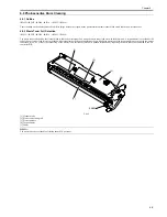
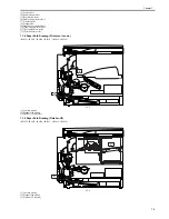
6.10.3 Transfer Charging Roller
6.10.3.1 Removing the Transfer Charging Roller
0017-8561
iR2022i / iR2025 / iR2030 / iR2018 / iR2022 / iR2018i
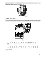
1) Open the left door.
2) Remove the transfer charging roller [1]
F-6-21
Do not touch the transfer charging roller surface.
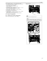
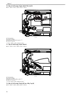
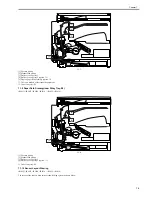
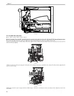
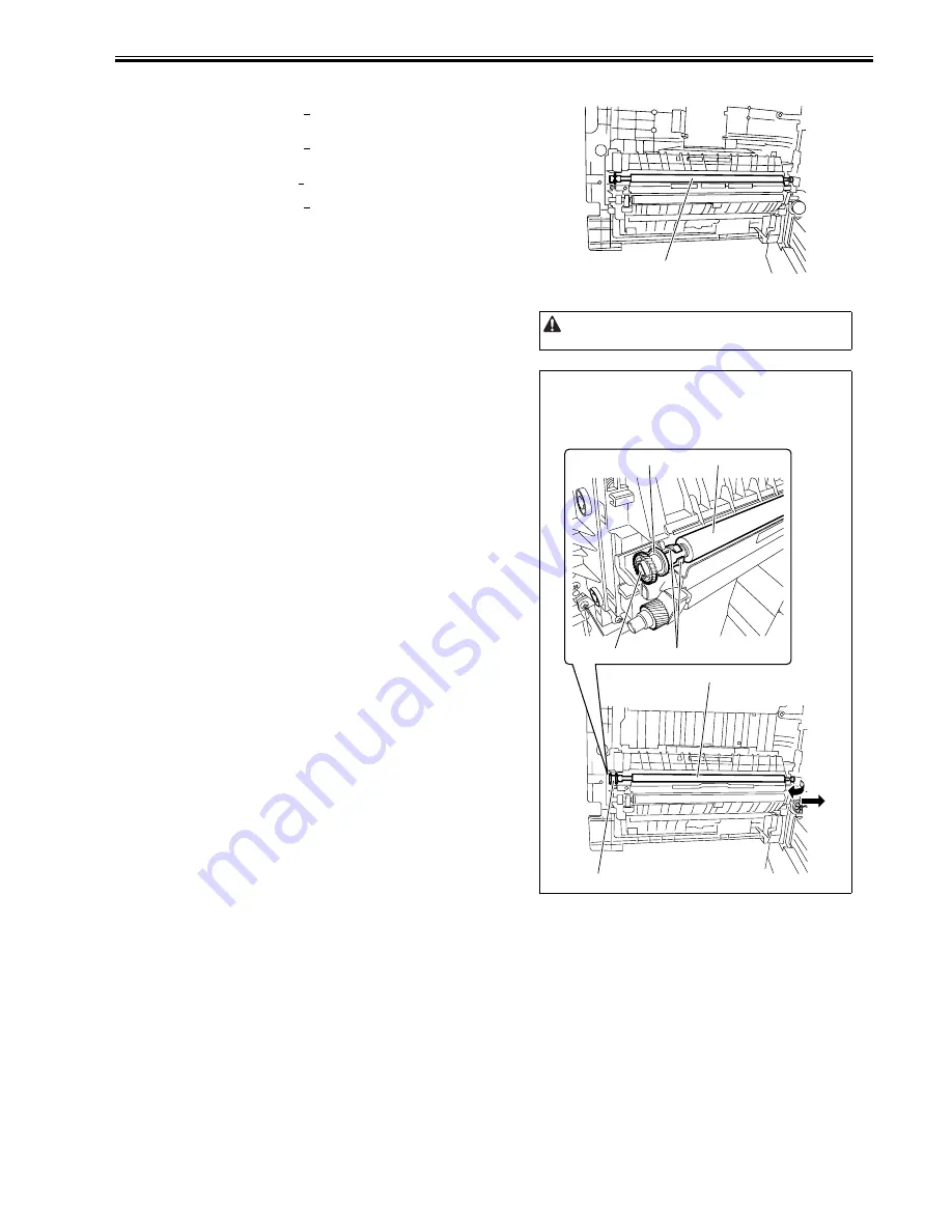
MEMO:
The transfer charging roller bearing [1] could be the same shape as the
figure below. If so, detach the transfer charging roller towards the arrow [3]
and [4]. Gear [5] will come off when detaching the transfer charging roller.
Be careful not to lose the gear [5]. When attaching the transfer charging
roller, apply transfer charging roller D cut[6] to gear [5] D cut.
[1]
[5]
[1]
[6]
[2]
[2]
[5]
[3]
[4]
Содержание imageRunner 2022
Страница 1: ...Aug 8 2007 Service Manual iR2030 2025 2022 2018 Series ...
Страница 2: ......
Страница 6: ......
Страница 20: ...Contents ...
Страница 21: ...Chapter 1 Introduction ...
Страница 22: ......
Страница 57: ...Chapter 1 1 33 ...
Страница 60: ......
Страница 61: ...T 1 11 ...
Страница 64: ......
Страница 65: ...T 1 12 ...
Страница 68: ......
Страница 69: ...Chapter 2 Installation ...
Страница 70: ......
Страница 72: ......
Страница 125: ...Chapter 2 2 53 ...
Страница 126: ......
Страница 127: ...Chapter 3 Main Controller ...
Страница 128: ......
Страница 130: ......
Страница 142: ......
Страница 143: ...Chapter 4 Original Exposure System ...
Страница 144: ......
Страница 170: ......
Страница 171: ...Chapter 5 Laser Exposure ...
Страница 172: ......
Страница 174: ......
Страница 181: ...Chapter 6 Image Formation ...
Страница 182: ......
Страница 184: ......
Страница 196: ......
Страница 197: ...Chapter 7 Pickup Feeding System ...
Страница 198: ......
Страница 217: ...Chapter 8 Fixing System ...
Страница 218: ......
Страница 220: ......
Страница 234: ......
Страница 235: ...Chapter 9 External and Controls ...
Страница 236: ......
Страница 255: ...Chapter 10 RDS ...
Страница 256: ......
Страница 258: ......
Страница 268: ......
Страница 269: ...Chapter 11 Maintenance and Inspection ...
Страница 270: ......
Страница 272: ......
Страница 275: ...Chapter 12 Standards and Adjustments ...
Страница 276: ......
Страница 278: ......
Страница 281: ...Chapter 12 12 3 ...
Страница 282: ......
Страница 283: ...Chapter 13 Correcting Faulty Images ...
Страница 284: ......
Страница 286: ......
Страница 299: ...F 13 11 F 13 12 1 2 3 4 5 6 7 8 9 10 11 12 13 14 15 16 17 ...
Страница 300: ......
Страница 301: ...Chapter 14 Self Diagnosis ...
Страница 302: ......
Страница 304: ......
Страница 317: ...Chapter 15 Service Mode ...
Страница 318: ......
Страница 381: ...Chapter 16 Upgrading ...
Страница 382: ......
Страница 384: ......
Страница 411: ...Chapter 17 Service Tools ...
Страница 412: ......
Страница 413: ...Contents Contents 17 1 Service Tools 17 1 17 1 1 Special Tools 17 1 17 1 2 Oils and Solvents 17 1 ...
Страница 414: ......
Страница 417: ...Aug 8 2007 ...
Страница 418: ......


