


Chapter 4
4-20
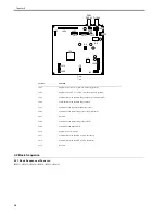
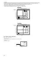
23) Remove the reader controller PCB [1] from the mount.
- Screws [2], 3 pcs
F-4-43
4.4.3 Scanner Motor
4.4.3.1 Removing the Scanner Motor
0017-8458
iR2022i / iR2025 / iR2030 / iR2018 / iR2022 / iR2018i
1) Detach the rear cover.
2) Open the front cover.
3) Detach the right cover (lower).
4) Detach the right cover (upper).
5) Detach the left cover (rear).
6) Open the copyboard cover (or ADF).
7) Detach the small cover.
8) Disconnect the ground cable of the ADF harness.
9) Remove the ADF harness.
10) Detach the reader rear cover.
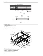
11) Remove the scanner motor.
- Connector [2], 1 pcs.
- Screw [3], 2 pcs.
- Spring [4], 1 pcs.
F-4-44
4.4.4 Contact sensor
4.4.4.1 Removing the Contact Image Sensor (CIS)
0017-8495
iR2022i / iR2025 / iR2030 / iR2018 / iR2022 / iR2018i
1) Detach the rear cover.
2) Open the front cover.
3) Detach the right cover (lower).
4) Detach the right cover (upper).
5) Detach the left cover (rear).
6) Open the copyboard cover (or ADF).
7) Detach the small cover.
8) Disconnect the ground cable of the ADF harness.
9) Remove the ADF harness.
10) Detach the reader rear cover.
11) Open the copyboard cover (or ADF).
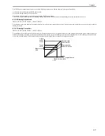
12) Remove the copyboard glass.
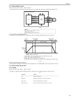
13) Pull the drive belt (front) [1] in the direction of the arrow to move the
contact sensor [2] to the position shown below.
F-4-45
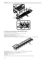
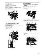
2) Remove the rear side of the contact sensor [1] from the carriage.
3) Disconnect the flexible cable [2], and then remove the contact sensor [1].
F-4-46
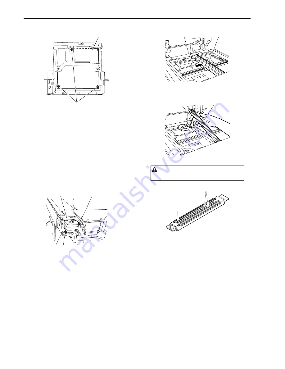
F-4-47
4.4.4.2 Procedure after Replacing the CIS(Touch panel
type)
0017-8498
iR2022i / iR2025 / iR2030 / iR2018i
After replacing the contact image sensor (CIS), go through the following
steps to perform inter-channel output correction:
1) Enter the service mode.
Sequentially press the Additional functions key, 2 key, 8 key, and Additional
functions key on the operation panel.
2) Press the arrow key on the touch panel to display "TEST MODE".
3) Press [OK].
4) Press the [2] key to display "SCAN TEST".
5) Press the [1] key to display "SHADING".
6) Press [OK].
After completion of the above procedure, the contact sensor output is com-
pensated and parameters are set automatically.
After completion of automatic adjustment, "OK" is displayed.
4.4.5 Copyboard Cover Open/Close Sensor
4.4.5.1 Removing the Copyboard Cover Open/Close
Sensor (Front/Rear)
0017-8499
iR2022i / iR2025 / iR2030 / iR2018 / iR2022 / iR2018i
1) Detach the rear cover.
2) Open the front cover.
3) Detach the right cover (lower).
[1]
[2]
[2]
[1]
[3]
[4]
[3]
When removing or installing the contact sensor unit, take care not to touch
the light guide and rod lens array.
[2]
[1]
[1]
[2]
Light guide
Rod lens array
Содержание imageRunner 2022
Страница 1: ...Aug 8 2007 Service Manual iR2030 2025 2022 2018 Series ...
Страница 2: ......
Страница 6: ......
Страница 20: ...Contents ...
Страница 21: ...Chapter 1 Introduction ...
Страница 22: ......
Страница 57: ...Chapter 1 1 33 ...
Страница 60: ......
Страница 61: ...T 1 11 ...
Страница 64: ......
Страница 65: ...T 1 12 ...
Страница 68: ......
Страница 69: ...Chapter 2 Installation ...
Страница 70: ......
Страница 72: ......
Страница 125: ...Chapter 2 2 53 ...
Страница 126: ......
Страница 127: ...Chapter 3 Main Controller ...
Страница 128: ......
Страница 130: ......
Страница 142: ......
Страница 143: ...Chapter 4 Original Exposure System ...
Страница 144: ......
Страница 170: ......
Страница 171: ...Chapter 5 Laser Exposure ...
Страница 172: ......
Страница 174: ......
Страница 181: ...Chapter 6 Image Formation ...
Страница 182: ......
Страница 184: ......
Страница 196: ......
Страница 197: ...Chapter 7 Pickup Feeding System ...
Страница 198: ......
Страница 217: ...Chapter 8 Fixing System ...
Страница 218: ......
Страница 220: ......
Страница 234: ......
Страница 235: ...Chapter 9 External and Controls ...
Страница 236: ......
Страница 255: ...Chapter 10 RDS ...
Страница 256: ......
Страница 258: ......
Страница 268: ......
Страница 269: ...Chapter 11 Maintenance and Inspection ...
Страница 270: ......
Страница 272: ......
Страница 275: ...Chapter 12 Standards and Adjustments ...
Страница 276: ......
Страница 278: ......
Страница 281: ...Chapter 12 12 3 ...
Страница 282: ......
Страница 283: ...Chapter 13 Correcting Faulty Images ...
Страница 284: ......
Страница 286: ......
Страница 299: ...F 13 11 F 13 12 1 2 3 4 5 6 7 8 9 10 11 12 13 14 15 16 17 ...
Страница 300: ......
Страница 301: ...Chapter 14 Self Diagnosis ...
Страница 302: ......
Страница 304: ......
Страница 317: ...Chapter 15 Service Mode ...
Страница 318: ......
Страница 381: ...Chapter 16 Upgrading ...
Страница 382: ......
Страница 384: ......
Страница 411: ...Chapter 17 Service Tools ...
Страница 412: ......
Страница 413: ...Contents Contents 17 1 Service Tools 17 1 17 1 1 Special Tools 17 1 17 1 2 Oils and Solvents 17 1 ...
Страница 414: ......
Страница 417: ...Aug 8 2007 ...
Страница 418: ......


