


Chapter 3
3-10
F-3-23
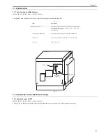
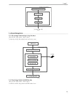
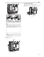
12) Detach the flexible cable guide [1].
- 3 screws [2]
F-3-24
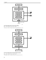
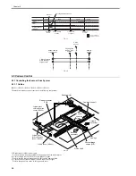
13) Detach the IP cover [1].
- 15 screws [2]
F-3-25
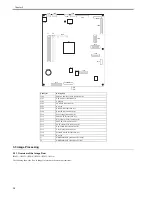
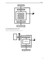
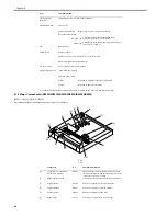
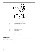
14) Detach the image processor PCB [1].
- 5 connectors [2]
- 7 screws [3]
F-3-26
3.5.1.3 Procedure after Replacing the Image Processor
PCB
0017-2271
iR2022i / iR2025 / iR2030 / iR2018 / iR2022 / iR2018i
If you have replaced the image processor PCB with a new one, perform the
following operations:
- Using the service support tool, download the latest firmware (System/
Boot).
- Input the all value printed on the service label affixed to the rear cover.
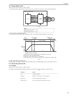
Make the following adjustments:
- Correction of output between CIS channels
1) Enter the service mode.
Sequentially press the User Mode key "
", 2 key, 8 key, and User Mode
key "
" on the operation panel.
2) Using the arrow keys on the operation panel, display "TEST MODE".
3) Press the OK key.
4) Press the 2 key. "SCAN TEST" appears.
5) Press the 1 key.
After completion of the above steps, contact sensor output correction will be
performed and parameters will be set automatically.
- Read position adjustment (Stream reading: Only when the ADF is installed)
1) Enter the service mode.
Press the User Mode key "
", 2 key, 8 key, User Mode key "
" on the
operation panel of the host machine.
2) Using the arrow keys on the operation panel, display "TEST MODE".
3) Press the OK key.
4) Press the 2 key. "SCAN TEST" appears.
5) Press the 3 key. "SHEET POS ADJ" appears.
The optical system starts scanning. Several seconds later, automatic adjust-
ment of the reading position finishes and "OK" appears.
3.5.2 SDRAM
3.5.2.1 Preparation for Removing the SDRAM
0017-2250
iR2022i / iR2025 / iR2030 / iR2018 / iR2022 / iR2018i
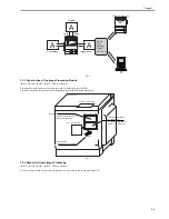
1) Detach the rear cover.
(page 9-5)
Reference[Removing the Rear Cover]
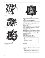
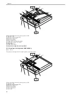
2) Change the position of the jumper plug (JP100) [1] on the modem PCB
(capacitor PCB).
[1]
[1]
[2]
[2]
[2]
[2]
[1]
[2]
If automatic adjustment fails, "NG" appears. Perform the following
procedure:
Clean the white roller of the DADF and the document glass of the host
machine, and then retry auto adjustment.
If disconnecting/connecting the modem PCB (capacitor PCB) without
implementing this operation, the SDRAM may be broken.
[3]
[3]
[1]
[2]
Содержание imageRunner 2022
Страница 1: ...Aug 8 2007 Service Manual iR2030 2025 2022 2018 Series ...
Страница 2: ......
Страница 6: ......
Страница 20: ...Contents ...
Страница 21: ...Chapter 1 Introduction ...
Страница 22: ......
Страница 57: ...Chapter 1 1 33 ...
Страница 60: ......
Страница 61: ...T 1 11 ...
Страница 64: ......
Страница 65: ...T 1 12 ...
Страница 68: ......
Страница 69: ...Chapter 2 Installation ...
Страница 70: ......
Страница 72: ......
Страница 125: ...Chapter 2 2 53 ...
Страница 126: ......
Страница 127: ...Chapter 3 Main Controller ...
Страница 128: ......
Страница 130: ......
Страница 142: ......
Страница 143: ...Chapter 4 Original Exposure System ...
Страница 144: ......
Страница 170: ......
Страница 171: ...Chapter 5 Laser Exposure ...
Страница 172: ......
Страница 174: ......
Страница 181: ...Chapter 6 Image Formation ...
Страница 182: ......
Страница 184: ......
Страница 196: ......
Страница 197: ...Chapter 7 Pickup Feeding System ...
Страница 198: ......
Страница 217: ...Chapter 8 Fixing System ...
Страница 218: ......
Страница 220: ......
Страница 234: ......
Страница 235: ...Chapter 9 External and Controls ...
Страница 236: ......
Страница 255: ...Chapter 10 RDS ...
Страница 256: ......
Страница 258: ......
Страница 268: ......
Страница 269: ...Chapter 11 Maintenance and Inspection ...
Страница 270: ......
Страница 272: ......
Страница 275: ...Chapter 12 Standards and Adjustments ...
Страница 276: ......
Страница 278: ......
Страница 281: ...Chapter 12 12 3 ...
Страница 282: ......
Страница 283: ...Chapter 13 Correcting Faulty Images ...
Страница 284: ......
Страница 286: ......
Страница 299: ...F 13 11 F 13 12 1 2 3 4 5 6 7 8 9 10 11 12 13 14 15 16 17 ...
Страница 300: ......
Страница 301: ...Chapter 14 Self Diagnosis ...
Страница 302: ......
Страница 304: ......
Страница 317: ...Chapter 15 Service Mode ...
Страница 318: ......
Страница 381: ...Chapter 16 Upgrading ...
Страница 382: ......
Страница 384: ......
Страница 411: ...Chapter 17 Service Tools ...
Страница 412: ......
Страница 413: ...Contents Contents 17 1 Service Tools 17 1 17 1 1 Special Tools 17 1 17 1 2 Oils and Solvents 17 1 ...
Страница 414: ......
Страница 417: ...Aug 8 2007 ...
Страница 418: ......


