


Chapter 3
3-8
3.5 Parts Replacement Procedure
3.5.1 Main Controller PCB
3.5.1.1 Preparation for Removing the Image Processor
PCB
0017-2248
iR2022i / iR2025 / iR2030 / iR2018 / iR2022 / iR2018i
1) Detach the rear cover.
(page 9-5)
Reference[Removing the Rear Cover]
2) Detach the rear left cover.
(page 9-5)
Reference[Removing the Rear Left
Cover]
3.5.1.2 Removing the Image Processor PCB
0017-2249
iR2022i / iR2025 / iR2030 / iR2018 / iR2022 / iR2018i
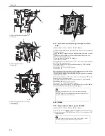
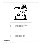
1) Change the position of the jumper plug (JP100) [1] on the modem PCB
(capacitor PCB).
F-3-13
2) Detach the RAM cover [1].
- 5 screws [2]
F-3-14
3) Detach the SDRAM.
(page 3-11)
Reference[Removing the SDRAM]
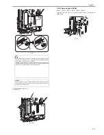
4) Detach the LAN cover [1].
- 6 screws [2]
F-3-15
5) Disconnect the connector [1] of the IP-LAN cable.
F-3-16
6) Detach the modem PCB or the capacitor PCB [1].
In the case of the modem PCB
- 3 connectors [2]
- 2 screws [3]
If disconnecting/connecting the modem PCB (capacitor PCB) without
implementing this operation, the SDRAM may be broken.
When turning off the main power switch and disconnecting the power plug
from the power outlet, the power is supplied between the SDRAM and the
super capacitor for image memory backup.
If the jumper plug (JP100) is disconnected with the image being backed up,
the contents in the memory are all cleared. Be sure to output all data in the
memory before disconnecting the jumper plug (JP100).
MEMO:
The jumper plug is small. A needlenose pliers or tweezers may be useful in
this operation. To prevent short-circuit, avoid contact of the jumper pin to a
nearby metal through the tool.
[1]
[1]
[1]
[2]
[1]
[2]
[2]
[1]
Содержание imageRunner 2022
Страница 1: ...Aug 8 2007 Service Manual iR2030 2025 2022 2018 Series ...
Страница 2: ......
Страница 6: ......
Страница 20: ...Contents ...
Страница 21: ...Chapter 1 Introduction ...
Страница 22: ......
Страница 57: ...Chapter 1 1 33 ...
Страница 60: ......
Страница 61: ...T 1 11 ...
Страница 64: ......
Страница 65: ...T 1 12 ...
Страница 68: ......
Страница 69: ...Chapter 2 Installation ...
Страница 70: ......
Страница 72: ......
Страница 125: ...Chapter 2 2 53 ...
Страница 126: ......
Страница 127: ...Chapter 3 Main Controller ...
Страница 128: ......
Страница 130: ......
Страница 142: ......
Страница 143: ...Chapter 4 Original Exposure System ...
Страница 144: ......
Страница 170: ......
Страница 171: ...Chapter 5 Laser Exposure ...
Страница 172: ......
Страница 174: ......
Страница 181: ...Chapter 6 Image Formation ...
Страница 182: ......
Страница 184: ......
Страница 196: ......
Страница 197: ...Chapter 7 Pickup Feeding System ...
Страница 198: ......
Страница 217: ...Chapter 8 Fixing System ...
Страница 218: ......
Страница 220: ......
Страница 234: ......
Страница 235: ...Chapter 9 External and Controls ...
Страница 236: ......
Страница 255: ...Chapter 10 RDS ...
Страница 256: ......
Страница 258: ......
Страница 268: ......
Страница 269: ...Chapter 11 Maintenance and Inspection ...
Страница 270: ......
Страница 272: ......
Страница 275: ...Chapter 12 Standards and Adjustments ...
Страница 276: ......
Страница 278: ......
Страница 281: ...Chapter 12 12 3 ...
Страница 282: ......
Страница 283: ...Chapter 13 Correcting Faulty Images ...
Страница 284: ......
Страница 286: ......
Страница 299: ...F 13 11 F 13 12 1 2 3 4 5 6 7 8 9 10 11 12 13 14 15 16 17 ...
Страница 300: ......
Страница 301: ...Chapter 14 Self Diagnosis ...
Страница 302: ......
Страница 304: ......
Страница 317: ...Chapter 15 Service Mode ...
Страница 318: ......
Страница 381: ...Chapter 16 Upgrading ...
Страница 382: ......
Страница 384: ......
Страница 411: ...Chapter 17 Service Tools ...
Страница 412: ......
Страница 413: ...Contents Contents 17 1 Service Tools 17 1 17 1 1 Special Tools 17 1 17 1 2 Oils and Solvents 17 1 ...
Страница 414: ......
Страница 417: ...Aug 8 2007 ...
Страница 418: ......


