background image

R

EPLACING


PARTS

37

T

O


REMOVE


AND


REPLACE


THE


FRONT


PANEL

N

OTE

:

To remove the front panel, you must first remove the left and right panels.

1 Remove the upper faceplate from the front of the chassis.

Press down to release the two tabs that secure the upper faceplate to the front panel, and then 
carefully remove the upper faceplate from the front panel.

N

OTE

:

You must remove the upper faceplate in order to remove the front panel from 

the chassis.

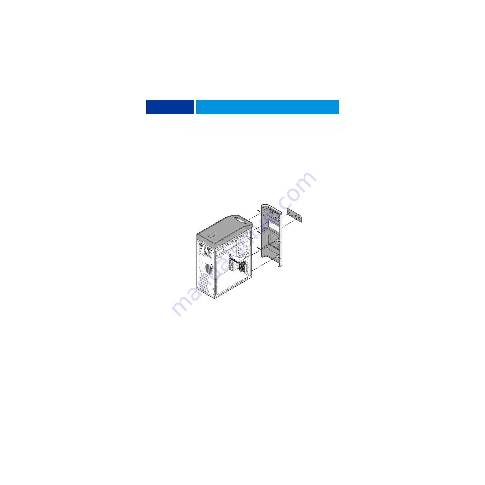
2 Pull outward on the six tabs that secure the front panel to the chassis, and then lift the panel 

off of the chassis.

First remove the two top tabs, then the two middle tabs, and then the two bottom tabs.

F

IGURE

 9:

Removing/replacing the front panel

3 To replace the front panel, align the four cutouts in the panel with the power and reset 

buttons and front USB ports.

4 Press the panel against the chassis to snap it into place.

Snap the tabs in pairs (first the top tabs, then the middle tabs, and then the bottom tabs).

5 Replace the upper faceplate.

Insert the two standoffs at the base of the faceplate into the chassis, and then carefully press 
the faceplate against the chassis to lock the faceplate into place.

Upper faceplate

Содержание imagePRESS Server F200

Страница 1: ...er F200 Installation and Service Guide A guide for service technicians Replacement parts and specifications are subject to change For a current parts list contact your authorized service support center 45127865 08 May 2014 ...

Страница 2: ...tation is subject to change without notice and does not represent a commitment on the part of EFI The documentation is further covered by Legal Notices distributed with this product The documentation may be provided in conjunction with EFI Software Software and any other EFI product described in the documentation The Software is furnished under license and may only be used or copied in accordance ...

Страница 3: ... environment 12 Tools you will need 13 INSTALLING HARDWARE 14 Installation sequence 14 Checking the customer site 15 Copier readiness 15 Setting customer expectations 16 Unpacking the imagePRESS Server 17 Connecting the imagePRESS Server 18 Connecting the monitor keyboard mouse and power 18 Connecting to the copier and the network 19 Configuring a static IP address for the imagePRESS Server 20 Com...

Страница 4: ...ernal components 33 Shutting down the system 33 Opening the imagePRESS Server 35 Removing and replacing boards 40 Copier interface board 40 User interface board assembly 41 Motherboard 45 Motherboard replacement overview 46 Removing the motherboard 47 Replacing the motherboard 51 Verifying new motherboard installation and transferring options and BIOS information 55 Replacing parts on the motherbo...

Страница 5: ...table media 83 Platform Utilities 83 Changing the factory default language 84 Installing system software 84 System updates 87 About backing up and restoring the imagePRESS Server and the system configuration 87 TROUBLESHOOTING 88 Preliminary on site checkout 88 Checking external connections 89 Checking internal components 89 Inspecting the system 90 Normal startup sequence 93 Error messages and co...

Страница 6: ...CONTENTS 6 Networking and connectivity 104 Safety and emissions compliance 105 Safety approvals 105 EMI EMC approvals 105 INDEX 106 ...

Страница 7: ...ng the side panels 36 FIGURE 9 Removing replacing the front panel 37 FIGURE 10 Removing replacing the top panel 38 FIGURE 11 Copier interface board component side 40 FIGURE 12 Diagram of the user interface board front and back 42 FIGURE 13 Removing replacing the user interface board 43 FIGURE 14 Removing replacing the UIB buttons 44 FIGURE 15 Motherboard 48 FIGURE 16 CPU cooling assembly 58 FIGURE...

Страница 8: ...rd disk drive from in the hard disk drive bracket 70 FIGURE 23 component sled with switch bank assembly 72 FIGURE 24 Removing replacing the component sled from the chassis 73 FIGURE 25 Removing replacing the switch bank assembly 74 FIGURE 26 Removing replacing the DVD drive 77 FIGURE 27 Normal startup sequence 93 ...

Страница 9: ...obe PostScript 3 color printing capability to the copier It is optimized for high speed network communications processing rasterization and printing of color and black and white pages As an integral part of a color printing system the imagePRESS Server enables users to Send images over TCP IP networks to imagePRESS Server supported devices Spool print jobs and select a printing priority for each j...

Страница 10: ...l does not support the weight of the system ATTENTION Ne jamais soulever le serveur d impression par sa partie supérieure celle ci ne peut pas supporter le poids du système AVVERTENZA Il server di stampa non deve essere mai sollevato afferrandolo dal pannello superiore in quanto quest ultimo non può sostenere il peso dell intero sistema WARNUNG Heben Sie den Druckserver nicht an der oberen Gehäuse...

Страница 11: ...erver LCD window breaks and the liquid crystal inside leaks out avoid contact If you come in contact with the liquid crystal immediately wash it off your skin with soap and water Use care when handling parts of the imagePRESS Server as some edges on the unit may be sharp Do not install third party applications onto the imagePRESS Server Third party applications are not supported and can cause syst...

Страница 12: ...new board When possible work on a ground connected antistatic mat Wear an antistatic grounding strap grounded at the same place as the antistatic mat If that is not possible do the following Attach a grounding strap to your wrist Attach the other end to a good ground When you unpack the imagePRESS Server from the carton for the first time touch a metal area of the copier to discharge the static on...

Страница 13: ...nd antistatic mat Flathead screwdriver 0 1 and 2 Phillips head screwdrivers Needlenose pliers imagePRESS Server documentation including the customer media pack and any related service bulletins Avoid touching magnetic tools to storage media such as hard disk drives Contact between magnetic tools and magnetic storage media may result in data corruption ...

Страница 14: ... and Utilities which are part of the user documentation set Installation sequence Because the imagePRESS Server is a node on the customer s computer network make sure that you coordinate your scheduled installation with the network administrator at the customer site For Network Setup information refer the network administrator to Configuration and Setup which is part of the user documentation set ...

Страница 15: ... Server Copier readiness Is the copier configured for use with the imagePRESS Server For the proper settings see the documentation that accompanies the copier Is space available near the copier for the imagePRESS Server and the furniture Make sure that adequate space is available for the imagePRESS Server and the furniture Allow enough space at the connector panel for the cables to route easily an...

Страница 16: ...network administrator must be available during the installation for network connectivity Equipment downtime and impact on the network can be minimized if the network administrator installs a network connector for the imagePRESS Server and confirms network functionality with the connector in place before the date scheduled for the imagePRESS Server installation The network administrator must make a...

Страница 17: ... erga o servidor de impressão pelo painel superior O painel superior não suporta o peso do sistema WAARSCHUWING Til de afdrukserver nooit op door het bovenpaneel vast te nemen Het bovenpaneel kan het gewicht van het systeem niet dragen TO UNPACK THE IMAGEPRESS SERVER 1 Open the box and remove the packing material Save the original boxes and packing material in case you need to transport the imageP...

Страница 18: ...uctions that accompany the furniture 2 Place the keyboard in the keyboard tray on the underside of the furniture table top Place the mouse on the table top 3 Connect the keyboard and mouse cables to the USB ports on the imagePRESS Server connector panel 4 If the monitor VGA cable is not already attached to the monitor attach it according to the instructions provided with the monitor Connect the ot...

Страница 19: ...pier NOTE The straight through network cable at the customer site and the Ethernet crossover cable included with the imagePRESS Server look similar but are not interchangeable Make sure that you connect the Ethernet crossover cable to the lower RJ 45 port on the imagePRESS Server connector panel FIGURE 2 Straight through and Ethernet crossover cables TO CONNECT TO THE NETWORK 1 Make sure that the ...

Страница 20: ...f the user documentation set NOTE The straight through network cable at the customer site and the Ethernet crossover cable included with the imagePRESS Server look similar but are not interchangeable Make sure that you connect the network cable to the upper RJ 45 port on the imagePRESS Server connector panel see page 28 Configuring a static IP address for the imagePRESS Server If the customer requ...

Страница 21: ... variety of sources for example System Updates see page 87 patches provided on CD or patches downloaded by the customer Windows operating system updates should be obtained from Microsoft directly Because such updates are available directly from Microsoft EFI does not maintain or provide them via the System Updates feature 5 Print a Test Page and a Configuration page and ask the customer to verify ...

Страница 22: ...lows you to do the following Eject CDs and DVDs a hardware eject button is also provided below the disc slot Replace the motherboard when the motherboard replacement dongle is inserted into a USB port View the IP address of the imagePRESS Server Shut down restart or reboot the imagePRESS Server see page 25 Interact with the imagePRESS Server during software installation see page 79 Run certain dia...

Страница 23: ...eboot System options Flashing amber The imagePRESS Server is starting up and the BIOS has established communication with the User Interface Board UIB Flashing green The imagePRESS Server is continuing startup and the Windows operating system has established communication with the UIB Solid green The imagePRESS Server is powered on and is in the Idle state Solid amber The imagePRESS Server is power...

Страница 24: ... interrupted and all currently processing jobs are aborted and may be lost Shut Down Server Shuts down all imagePRESS Server server software and powers off the system Always select this option to power off the system NOTE Avoid using the reset button on the front panel as doing so may cause the system to operate unpredictably Use the reset button on the front of the imagePRESS Server only if the s...

Страница 25: ...ach any cables to it NOTE Use the reset button on the front of the imagePRESS Server only if the system is unresponsive to keyboard or mouse actions TO START THE IMAGEPRESS SERVER 1 Make sure that the power cable is attached and that the power switch is in the ON position 2 Press the power button on the front panel 3 Check the Activity light on the control panel The power supply automatically sens...

Страница 26: ...tion To restart or reboot the imagePRESS Server select Restart Server A submenu displays allowing you to select Restart Server Reboot System or Cancel To shut down the imagePRESS Server immediately select Shut Down System NOTE Use the reset button on the front of the imagePRESS Server only if the system is unresponsive to keyboard or mouse actions Allow the system to shut down and power off or res...

Страница 27: ...e control panel the imagePRESS Server is processing You must wait until the system finishes and reaches Idle before restarting or shutting down If the system has just finished processing wait at least five seconds after the system reaches Idle before beginning the shutdown procedure 2 From the copier control panel press Main Menu button If the Fiery icon does not appear on the copier touch panel p...

Страница 28: ... drive Replacement parts are available from your authorized service representative The terms replace and replacing are used throughout this document to refer to the reinstallation of existing components Install new components only when necessary If you determine that a component that you have removed is not faulty reinstall it NOTE Replacement parts and specifications are subject to change Install...

Страница 29: ... the reset button only if the system is unresponsive to keyboard or mouse actions 6 USB port 7 USB port 8 Power connector 9 Power switch Power On O Power Off 10 Network port 11 DVI port not used 12 Monitor VGA port 13 USB ports keyboard mouse 14 Ethernet crossover port 15 USB ports 16 Copier interface ports Connector panel Front panel 10 1 2 3 4 5 6 7 8 9 11 12 13 14 15 6 1 ...

Страница 30: ... 2 Motherboard 3 Network port 4 Monitor VGA port 5 USB ports and Ethernet crossover port 6 USB ports 7 Copier interface board 8 CPU cooling assembly 9 DIMM slots 10 DVD drive 11 Removable drive 12 Hard disk drive in bracket 13 Front fan 10 1 2 3 4 5 6 7 8 9 11 12 13 ...

Страница 31: ...ive 7 Front panel 8 Upper faceplate 9 UIB cable 10 Hard disk drive bracket 11 Hard disk drive 12 Side panel left 13 Hard disk drive data cables 14 DVD drive power data combination cable 15 CPU cooling assembly 16 Copier interface board 17 DIMMs 18 Battery 19 CPU 20 Motherboard 21 Fan 22 Chassis 23 Power supply 24 Side panel right NOTE UIB buttons CPU fan cable tie wraps cable clamps dongle s and e...

Страница 32: ...USB_A 4 Power and reset cables Front panel Motherboard connector J20 5 Speaker cable Front panel Motherboard connector J83 6 Front panel fan cable Front panel fan Motherboard connector FRONT FAN 7 DVD drive power data combo cable DVD drive Motherboard connector SATA 0 8 Hard disk drive data cable Hard disk drive Motherboard connector SATA 1 9 CPU fan cable CPU fan Motherboard connector CPU FAN If ...

Страница 33: ...ssing the internal components Remember that when the imagePRESS Server is powered off network access to the copier is interrupted Always obtain permission from the network administrator before you take the imagePRESS Server off the network If you are cycling power wait at least 10 seconds before powering back on If you are unable to shut down the imagePRESS Server through the control panel power o...

Страница 34: ...ssing wait at least five seconds after the system reaches Idle before beginning the shutdown procedure 2 If the logo screen is displayed press the Menu button once to display the Functions menu 3 Select Shut Down System NOTE Use the reset button on the front of the imagePRESS Server only if the system is unresponsive to keyboard or mouse actions Allow the system to shut down and power off Before a...

Страница 35: ...pelo painel superior O painel superior não suporta o peso do sistema WAARSCHUWING Til de afdrukserver nooit op door het bovenpaneel vast te nemen Het bovenpaneel kan het gewicht van het systeem niet dragen TO OPEN THE IMAGEPRESS SERVER 1 Shut down the imagePRESS Server see page 33 2 Remove all cables from the back of the imagePRESS Server 3 Remove the imagePRESS Server from the furniture see page ...

Страница 36: ...he panel off the chassis FIGURE 8 Removing replacing the side panels 3 To replace the panel fit the front edge of the panel on the pivot post in the chassis 4 Rotate the panel closed against the back of the chassis and replace the screws that you removed earlier Make sure not to damage cables as you replace the panel Fold all cables inside the chassis before closing the panel against the chassis P...

Страница 37: ...cure the front panel to the chassis and then lift the panel off of the chassis First remove the two top tabs then the two middle tabs and then the two bottom tabs FIGURE 9 Removing replacing the front panel 3 To replace the front panel align the four cutouts in the panel with the power and reset buttons and front USB ports 4 Press the panel against the chassis to snap it into place Snap the tabs i...

Страница 38: ...Slide the top panel a few inches toward the front of the chassis to disengage the hooks in the panel from the slots in the top of the chassis NOTE You may need to tap the back edge of the panel toward the front of the chassis to disengage the panel 3 Detach the UIB cable from the motherboard 4 Remove the panel from the chassis Carefully route the UIB cable out of the hole in the top of the chassis...

Страница 39: ... into the slots in the top of the chassis and then slide the top panel toward the back of the chassis to engage the hooks NOTE You may need to tap the front edge of the panel toward the back of the chassis to engage the panel completely 7 Replace the plug on the top panel Correctly align the plug and then place it into the receptacle on the top panel Secure the plug by replacing the locking bolt t...

Страница 40: ... processes the image data and sends it to the copier through the copier interface cable available on the imagePRESS Server connector panel FIGURE 11 Copier interface board component side TO REMOVE THE COPIER INTERFACE BOARD 1 Shut down and open the imagePRESS Server see pages 33 and 35 To remove the copier interface board you must remove the left panel 2 Make sure that the copier interface cables ...

Страница 41: ...ce board edge connector is keyed to fit in the motherboard connector only when properly oriented 2 Reassemble the imagePRESS Server and verify its functionality see page 78 User interface board assembly The user interface board UIB provides the interface between the imagePRESS Server and the user The front of the UIB contains circuitry for the following Activity lights amber green and red LEDs Dis...

Страница 42: ...face board to connector USB_A on the motherboard see Figure on page 48 FIGURE 12 Diagram of the user interface board front and back Back Front Line selection button pads UIB cable connector USB_A Activity lights LEDs Display window Up button pad Menu button pad Down button pad Jewel lights ...

Страница 43: ... from the connector on the back of the UIB Detach the UIB cable by grasping the cable connector Avoid pulling on the cable 4 Remove the four screws that secure the UIB to the underside of the top panel 5 Remove the UIB from the top panel Be sure to remove the plastic lens that covers the display window of the UIB FIGURE 13 Removing replacing the user interface board 6 If you are removing the UIB t...

Страница 44: ...dow of the UIB 5 Secure the UIB to the underside of the top panel Grasp the UIB in one hand while using the other hand to hold the plastic lens steady against the UIB display window Place the UIB in the mounting area of the top panel and carefully fit the buttons through the cutouts in the top panel as you hold the plastic lens in place Replace the four screws that secure the UIB to the underside ...

Страница 45: ...therboard review the troubleshooting and motherboard cautions on page 51 The CPU mounted on the motherboard controls the image data transferred to and from the copier interface The motherboard also controls hard disk drive functions and the communication between the imagePRESS Server and external devices ...

Страница 46: ...e Replace the motherboard Connect the motherboard replacement dongle Enter Service Mode and verify the new motherboard installation Reinstall the old motherboard Return the new motherboard and dongle to inventory Are test pages printed successfully Transfer options and BIOS information to the new motherboard Yes No See page 68 See page 84 See page 51 See page 55 See page 56 See page 68 NOTE Each p...

Страница 47: ...set button cable speaker cable front panel USB port cables and UIB cable This section also includes information about the following Replacing or adding DIMMs Replacing the CPU Replacing the battery Jumper configurations Follow standard ESD and other safety precautions when handling components see page 12 During service to the motherboard avoid using excessive force and always place the motherboard...

Страница 48: ...4 13 DIMM 3 14 CPU fan power CPU FAN 15 Speaker J83 16 UIB cable USB_A 17 SATA 0 DVD drive data connection 18 SATA 1 Hard disk drive data connection 19 Power and Reset J20 20 Front panel USB ports FP_USB_2 21 Front panel fan FRONT FAN 22 Clear CMOS Jumper J4 23 Auxiliary LED light Jumper AUX_POWER_LED1 MH Mounting holes NOTE Arrows indicate positions for inserting cable and jumper connections 16 M...

Страница 49: ...t you can reinstall the board in the same slot later 3 Remove the following cables from the old motherboard NOTE First remove any plastic cable clamp s securing internal cables and tie wraps Front panel fan cable Reset button cable Power button cable Speaker cable UIB cable Front panel USB port cables DVD drive cables SATA data cable Power and data combination cable Hard disk drive cables SATA dat...

Страница 50: ...to remove the hard disk drive 2 Remove all the mounting screws securing the motherboard to the chassis for screw locations see page 47 3 Remove the motherboard from the chassis Lift the edge of the motherboard Make sure that the motherboard connectors clear the chassis while you lift it out of the chassis Do not touch the contacts and avoid using excessive force During service avoid using excessiv...

Страница 51: ...ggested actions in the order listed If troubleshooting strategies checking cables and connections reinstalling system software and so forth do not solve the problem and you suspect that the hard disk drive or the motherboard is faulty always troubleshoot in the following order Troubleshooting in the wrong order will cause the system to malfunction In general it is highly unlikely that both the har...

Страница 52: ... remain in Service Mode indefinitely Use Service Mode to carefully verify the new motherboard before transferring options to the new motherboard Transferring options to the new motherboard permanently customizes the new motherboard Once customized the motherboard cannot be returned to inventory or installed in another imagePRESS Server If the new motherboard does not solve the problem in Service M...

Страница 53: ...BIOS chip from the old motherboard onto the new motherboard Doing so can damage the imagePRESS Server BIOS chips are not interchangeable 2 Install the motherboard in the chassis Angle the motherboard so that the motherboard connectors fit into the cutouts in the back of the chassis Make sure that the flexible grounding tabs on the cutouts for the network ports make contact with the outside of the ...

Страница 54: ...rt cables Speaker cable Power button cable Reset button cable Front panel fan cable 3 Secure cables as necessary with any plastic cable clamp that you may have removed earlier 4 Replace the copier interface board see page 48 for the location Make sure to install the board mounting bracket screw to secure the board to the chassis Press down firmly on the top of the board as you insert the screw NOT...

Страница 55: ... to transfer options to the new motherboard described below do not install system software and do not replace the hard disk drive Reinstall the old motherboard and return the new motherboard and the unused motherboard replacement dongle to inventory You may then perform additional service and troubleshooting procedures Transferring options for example Fiery Graphic Arts Premium Edition if applicab...

Страница 56: ...rboard was not the source of the problem and does not need to be replaced If so do not transfer options to the new motherboard described on page 55 do not install system software and do not replace the hard disk drive Reinstall the old motherboard and return the new motherboard with the unexpended motherboard replacement dongle to inventory For more information about troubleshooting system problem...

Страница 57: ...ly approved DIMMs available from your service representative DIMMs must be installed in matched pairs A matched pair is comprised of two alternate sockets DIMMs within a pair must be identical same capacity and same number of chips on each side For example in a two DIMM configuration populate DIMM 1 and DIMM 2 with DIMMs of identical capacity with the same number of chips on each side TO REPLACE A...

Страница 58: ... the motherboard from the chassis see page 47 disconnect the CPU fan cable from the motherboard and then remove the cooling assembly from the imagePRESS Server see page 59 The CPU cooling assembly consists of a fan and a heatsink NOTE Do not remove the CPU fan from the heatsink FIGURE 16 CPU cooling assembly Fastener screw 1 of 4 CPU fan Heatsink CPU Yellow triangle Load plate open Yellow triangle...

Страница 59: ...Server see pages 33 and 35 To access the CPU you must remove the left panel 2 Remove the CPU fan cable from motherboard connector CPU FAN 3 Remove the CPU cooling assembly Be aware that both the cooling assembly and the CPU may be very hot You may need to allow the components to cool before you attempt to remove them Loosen the four screws that secure the cooling assembly to the motherboard Partia...

Страница 60: ...the motherboard to install it on a new motherboard make sure that you completely remove any thermal compound residue on the surface of the CPU and at the base of the heatsink It may help to scrape all the residue off of the surface using the flat edge of something non conductive 5 Prepare the CPU socket by ensuring that The socket lever is in the open position The load plate is open 6 Place the CP...

Страница 61: ...d the fan cable easily reaches the CPU fan power connector CPU FAN on the motherboard 2 Place the cooling assembly on the CPU Make sure that the thermal pad on the underside of the heatsink is positioned on top of the CPU Be sure to remove any protective material that may be covering the surface of the thermal pad Otherwise the CPU may overheat Align the four screws with the four screw posts Tight...

Страница 62: ...nytt samme batteritype eller en tilsvarende type anbefalt av apparatfabrikanten Brukte batterier kasseres i henhold til lokal lovgivning VARNING Risk för explosion om batteriet byts ut mot en felaktig batterityp Byt bara ut batteriet mot en batterityp som har godkänts av tillverkaren Hantera använda batterier enligt lokal miljölagstiftning CUIDADO Existe peligro de explosión si la batería se susti...

Страница 63: ... its functionality see page 78 8 Configure the time and date in Setup see Configure Help for more information Failure to configure the time and date will cause the imagePRESS Server to hang when user software is being installed on the imagePRESS Server See page 100 Jumpers Jumper configurations should not be changed Jumper Description J4 J4 is the Clear CMOS and Password jumper Default configurati...

Страница 64: ...rd connector FRONT FAN 3 Release the fan from the fan bracket by bending the hooks on the bracket FIGURE 19 Removing the fan 4 Remove the fan from the chassis TO REPLACE THE FAN 1 Align the fan An arrow on the side of the fan indicates the airflow direction Make sure that the fan is positioned so that the arrow points inside the imagePRESS Server and the fan cable extends downward toward the mothe...

Страница 65: ...onnector ATX24P_1 5 Remove the 4 pin CPU power cable from motherboard connector J24 6 Remove the tie wrap securing the power cables to the chassis support beam 7 Remove the ferrites that are installed around the hard disk drive power cables Carefully pry open the latches on the sides of the ferrites and remove the ferrites from the cables Set the ferrites aside so that you can replace them later 8...

Страница 66: ...REPLACING PARTS 66 FIGURE 20 Removing replacing the power supply Screw 1 of 4 Power supply Connector panel Power supply cables Chassis support beam Screw ...

Страница 67: ...wer cable to motherboard connector ATX24P_1 5 Connect the power and data combination cable to the DVD drive 6 Install the ferrite around the hard disk drive power cable Use the ferrite that you removed earlier Place the ferrite around the cable near the connector and snap the edges of the ferrite closed 7 Connect the power cable to the hard disk drive Connect the thin black SATA power cable connec...

Страница 68: ...m software and then check to see if the problem persists If it does perform other procedures such as replacing the motherboard see page 51 Proper handling Improper handling can damage a hard disk drive Handle the hard disk drive with extreme care Use proper ESD practices when grounding yourself and the imagePRESS Server Keep magnets and magnetic sensitive objects away from the hard disk drive Do n...

Страница 69: ... from the hard disk drive 5 Remove the screw securing the hard disk drive bracket to the bracket shelf 6 Slide the hard disk drive bracket off the shelf and lift it out of the chassis see Figure 21 Unlock the hard disk drive bracket by moving the latch toward the connector panel and then sliding the bracket off the bracket shelf Avoid striking the DIMMs as you remove the hard disk drive bracket NO...

Страница 70: ...ws on the hard disk drive cover Loosening these hard disk drive screws breaks the seal and voids the hard disk drive warranty Do not touch the drive with magnetic objects such as magnetic screwdrivers and avoid placing magnetic sensitive objects such as credit cards and employee ID cards near the hard disk drive Replacement hard disk drives are not shipped with preinstalled system software After y...

Страница 71: ... all the way onto the shelf and lock it by moving the latch toward the front panel Avoid striking the DIMMs as you replace the hard disk drive bracket NOTE You will encounter slight resistance as you slide the bracket onto the shelf The resistance is caused by two tension points on the bottom of the bracket The resistance helps control the bracket s movement during removal and installation 5 Secur...

Страница 72: ...nents DVD drive Power button and cable Reset button and cable Speaker and cable Front USB ports and cables NOTE For more information about servicing the DVD drive see page 76 FIGURE 23 component sled with switch bank assembly Switch bank assembly with DVD drive Component sled Guide latch 1 of 2 NOTE Copier interface and internal cables are not shown ...

Страница 73: ...therboard Carefully pry open the latch on the side of the ferrite and remove the ferrite from the cables Set the ferrite aside so that you can replace it later 4 Unharness the cables from the cable clamp s and tie wraps inside the chassis 5 Remove the component sled from the chassis see Figure 23 on page 72 Press the guide latches on the sides of the component sled and carefully pull the sled out ...

Страница 74: ...t out of the component sled FIGURE 25 Removing replacing the switch bank assembly NOTE Guide the cables as you remove the assembly from the component sled Be careful not to damage the EMI gasket around the opening in the component sled 7 If you are removing the switch bank assembly to replace it with a new assembly remove the DVD drive see page 76 Component sled Switch bank assembly Screw 1 of 3 ...

Страница 75: ...f the switch bank assembly in through the chassis so that the cables are within reach of their connectors on the motherboard Slide the sled into the front of the chassis until the guide latches click into place NOTE Be careful not to damage the EMI gasket around the slot in the chassis when installing the component sled 4 Connect the following cables see Figure on page 48 for the location of conne...

Страница 76: ...ront panels the component sled and the switch bank assembly 2 Remove the power and data combination cable from the back of the DVD drive 3 Remove the component sled from the chassis and then remove the switch bank assembly from the component sled see page 73 4 Remove the four screws that secure the DVD drive to the switch bank assembly Set aside the screws so that you can replace them later NOTE O...

Страница 77: ...l the component sled in the chassis see page 75 3 Attach the power and data combination cable to the back of the DVD drive 4 If you installed a new DVD drive make sure to reset the time and date in Setup see Configure Help for more information 5 Reassemble the imagePRESS Server and verify its functionality see page 78 Switch bank assembly Screw 1 of 4 DVD drive NOTE Some switch bank assemblies hav...

Страница 78: ... wrap 2 Restore the imagePRESS Server to the upright position 3 Replace any panels that you removed earlier as described on page 35 4 If you replaced the motherboard make sure that the new motherboard solves the problem that you are troubleshooting and then transfer options to the new motherboard see page 55 5 If the imagePRESS Server is to be mounted on the furniture with the monitor see the reas...

Страница 79: ...re the imagePRESS Server to the factory default setting You must install the system software using the System Software DVDs only when you replaced the hard disk drive or restoring the backup does not solve the problem you are troubleshooting It is recommended to create a backup of the entire hard disk drive after you install the system software and run the initial Setup To create the backup or res...

Страница 80: ...install the documentation files after you finish installing the system software Custom simulation and output profiles Custom simulation and custom output profiles saved on the hard disk drive are deleted when you install system software Ask the site administrator to save a copy of any custom profiles to a CD or network location before you install software Make sure to use Backup Restore to create ...

Страница 81: ...an perform the backup management tasks from this option NOTE You can use the imagePRESS Server control panel to operate the Fiery System Installer You can also use a monitor mouse and keyboard attached if available TO START THE FIERY SYSTEM INSTALLER 1 Insert the System Software 1 DVD into the DVD drive of the imagePRESS Server 2 Restart the imagePRESS Server see page 25 3 Select the language you ...

Страница 82: ... you recover from a system crash you must restore the system with a backup image Backed up data can be only restored to the same imagePRESS Server TO RESTORE THE SYSTEM USING THE FIERY SYSTEM INSTALLER 1 Start the Fiery System Installer 2 If your backup file is stored in the USB drive or external hard disk attach the device to the imagePRESS Server 3 From What do you want to do screen select Resto...

Страница 83: ... startup screen the system did not enter the BIOS setup mode Restart the imagePRESS Server and repeat this step 5 Select the option to change the boot order and select the item starting from UEFI The name of the bootable media appears next to UEFI for example UEFI FLASH Drive AU_USB20 8 07 6 Save the BIOS settings and exit the BIOS setup mode Fiery System Installer starts in the same language that...

Страница 84: ...language under Server Language 3 Save your changes Changing languages takes three to five minutes Installing system software imagePRESS Server system software is provided on the following media System Software DVDs contain the Windows operating system software and the Fiery Server software User Software DVD contains the imagePRESS Server user software Install system software in the following cases...

Страница 85: ...ree minutes Do not push any buttons while the system is rebooting 6 When the Language Select screen displays select a language 7 When the What do you want to do screen displays choose New Installation 8 When the This installation will erase all data on the hard disk drive s Continue message appears choose Continue 9 At the prompt for each DVD insert System Software 2 DVD and then System Software 3...

Страница 86: ...ormation see Configuration and Setup The system reboots after you exit Setup 16 Reinstall any required software patches If you reinstalled the same version of system software be sure to reinstall all software patches that were previously installed on the imagePRESS Server For a list of previously installed patches see the Configuration page that you printed earlier If you installed an upgraded ver...

Страница 87: ...Depending on how it is configured System Updates operates manually or automatically For more information about how to schedule System Updates see Configuration and Setup which is part of the user documentation set Microsoft Windows operating system updates should be obtained from Microsoft directly Because such updates are available directly from Microsoft EFI does not maintain or provide them via...

Страница 88: ... to send to EFI Technical Support When performing the service procedures described in this chapter follow the precautions listed in page 10 Preliminary on site checkout Most problems with the imagePRESS Server are caused by loose board or cable connections This section describes the quick checks that you can do to locate and fix obvious problems It describes how to eliminate any problems with exte...

Страница 89: ...To review the safety precautions see page 10 TO CHECK INTERNAL COMPONENTS 1 Shut down and then open the imagePRESS Server see page 33 2 Before you touch any components inside the imagePRESS Server attach a grounding strap to your wrist and discharge any static electricity on your body by touching a metal part of the imagePRESS Server 3 Inspect the inside of the imagePRESS Server Make sure that no ...

Страница 90: ...ge references When the problem occurs verify that Power cable is connected properly into the power outlet Chassis fan is operating Network link activity LED on RJ 45 connector is blinking All external cables required are present in correct connectors and well seated Cables cable connectors and mating connectors appear undamaged External connectors chassis fan and power button page 89 and page 89 I...

Страница 91: ...t oxidized DIMMs for imagePRESS Server page 57 Each board required is Present Installed in the correct slot Well seated Appears undamaged Required cables if applicable are Present Firmly connected in the correct connectors Not visibly damaged Copier interface page 40 User interface board UIB is Present Correctly attached to its bracket Appears undamaged UIB cable is Present Firmly connected in the...

Страница 92: ...rd disk drive required is Present Correctly installed Not visibly damaged Jumpered as the master primary according to label Hard disk drive data cable is Present Firmly connected to motherboard connector SATA 1 Not visibly damaged Hard disk drive page 68 The drive required is Present Correctly installed Not visibly damaged Jumpered as the master secondary according to label Activity LED lights on ...

Страница 93: ...ouse and keyboard are connected to the correct ports on the imagePRESS Server connector panel The cables required are Present Installed in the correct connector Well seated Not visibly damaged including connectors Mouse if applicable Monitor if applicable Keyboard if applicable Monitor power cord not pictured TABLE 1 Verifying the system Conditions to verify Part and additional page references Cod...

Страница 94: ...system software and so forth do not solve the problem and you suspect that the hard disk drive or motherboard is faulty note that it is highly unlikely that the hard disk drive and the motherboard are both defective therefore avoid replacing both to solve one problem Always troubleshoot in the following order 1 Replace the hard disk drive and install system software Always replace a faulty hard di...

Страница 95: ... not connected to the motherboard the user interface board or both Faulty power cable Faulty power supply power supply may not be supplying power to the motherboard The CMOS jumper is not in the default position Faulty motherboard motherboard power plane may not be supplying power to components 1 Recheck all cables and connections 2 Make sure the connector panel power switch is in the ON position ...

Страница 96: ...with the firmware on the new user interface board Wait five minutes power off using the power button wait 10 seconds and then press the power button to power on again NOT following installation of a new user interface board system stops responding at this screen Possibly one of the following Faulty BIOS Faulty motherboard 1 Recheck all cables and connections 2 Reboot the imagePRESS Server 3 If the...

Страница 97: ...een and Activity light appear as follows Possibly one of the following Faulty disk in the DVD drive Faulty motherboard 1 Reboot the imagePRESS Server 2 If the problem occurs when you are installing software from bootable media DVD or CD the media may be damaged Try another DVD or CD 3 If the problem persists replace the motherboard see page 51 The following screen and Activity light appear as foll...

Страница 98: ...3 6 If the problem persists replace the motherboard see page 51 Control panel messages Could not mount the dos boot partition When transferring options following installation of a new motherboard page 56 you used the Feature Update CD The imagePRESS Server does not support the Feature Update CD Obtain the motherboard replacement dongle and follow the procedure on page 56 Control panel functions im...

Страница 99: ...gs periodically Possibly one of the following Board or cable connections are loose or faulty System software is corrupted Missing or faulty DIMM s CPU is overheated or faulty Motherboard is faulty 1 Recheck all cables and connections 2 Make sure that the CPU is firmly seated in its socket and that the fan cable is connected to the motherboard 3 If the problem persists restore the backup or reinsta...

Страница 100: ...tarting with the System Software DVD see page 84 2 If the problem persists obtain another User Software DVD and begin software installation again starting with the System Software DVD see page 84 3 If the problem persists you may need to replace the DVD drive see page 76 If replacing the DVD drive does not correct the problem reinstall the old DVD drive in the system 4 If the problem persists repl...

Страница 101: ... 4 If the rest of the network is functioning properly and the problem persists replace the motherboard see page 51 System starts up slowly then displays one or more DHCP error messages on the control panel Possibly one of the following Network cable is connected to the wrong RJ 45 port No cable wrong type of cable is connected to the network port Network cable or connection is faulty Network is fa...

Страница 102: ... the imagePRESS Server back on 2 If the problem persists replace the copier interface cables and board see page 40 3 If the problem persists you may need to service the copier The imagePRESS Server appears in the list of printers on the customer s workstation but certain jobs do not print A PostScript error 1 Make sure that Print to PostScript Error in Setup is set to Yes 2 Check for error message...

Страница 103: ...necessary See the service documentation that accompanies the copier Print quality is poor Possibly one of the following A file or application problem A missing or outdated printer description file The application cannot find the appropriate printer description file The system is out of calibration 1 Print a imagePRESS Server Test Page 2 If the quality of the imagePRESS Server Test Page is good the...

Страница 104: ...r cable upper port 1TB hard disk drive standard Built in DVD drive Physical specifications Operating Environment Temperature 5 C to 40 C Relative Humidity 10 85 non condensing Power Supply Voltage Input 100 240V 50 60Hz Power Supply Current Input 100V 6A Max 240V 3A Max Rated Power Consumption 350W Dimensions Height x Depth x Width 48 5 cm 19 1 in x 48 3 cm 19 0 in x 21 5 cm 8 5 in Weight 17 6 kg ...

Страница 105: ...0 1 2007 TUV NRTL CAN CSA 22 2 60950 1 07 TUV NRTL GS mark by TUV EN60950 1 2006 A11 A1 A12 2nd edition certificate and critical component part list EMI EMC approvals FCC Part 15 Verification NA Class A ICES 003 NA Class A EN55022 2010 EU Class A C TICK mark Australia and New Zealand EN55024 2010 EU Class A EN61000 3 2 2006 Plus A1 2009 A2 2009 EU Class A EN61000 3 3 2008 EU Class A EN62311 2008 E...

Страница 106: ...or service calls 15 21 78 clearing the CMOS 63 clock 99 closing the system 78 CMOS 63 troubleshooting start up problems 95 color profiles 80 Command WorkStation 9 component sled 72 73 76 components checking 89 exploded view of 31 Configure tool using to change the server s default language 14 84 configuring a static IP address 20 80 86 101 connections checking 89 connectors network 20 29 89 panel ...

Страница 107: ...an CPU 58 59 front panel 64 ferrite installing on the front panel USB port cables 75 installing on the power supply 67 removing from the front panel USB port cables 73 removing from the power supply 65 Fiery Scan 9 Fiery System Installer 79 Fiery 1 password 56 Font list definition 80 printing prior to HDD replacement 69 printing prior to system software installation 80 front panel 29 fan 64 layout...

Страница 108: ...0 normal startup sequence 93 O opening the system 35 P panels removing 35 37 password 56 Portable Document Format PDF 9 PostScript 9 power AC cable 89 AC connector 89 CPU fan 59 61 DVD drive 77 front panel fan 64 HDD 71 power and reset cables 32 precautions 16 power and reset buttons 72 power supply cables 65 removing 65 replacing 67 voltages 21 25 65 104 power AC connector 29 precautions 13 14 pr...

Страница 109: ...artup problems 95 system performance 99 100 twisted pair network cable 20 U UIB cable routing diagram 32 unpacking 17 up button 22 41 updating software 87 updating the system 55 USB ports 72 89 user interface board UIB activity light 41 buttons on 44 description 41 display window 41 line selection buttons move left right buttons 41 menu button 41 removing 43 replacing 44 up down buttons 41 user so...

Отзывы: