Chapter 2
2-1
2.1 Basic Construction
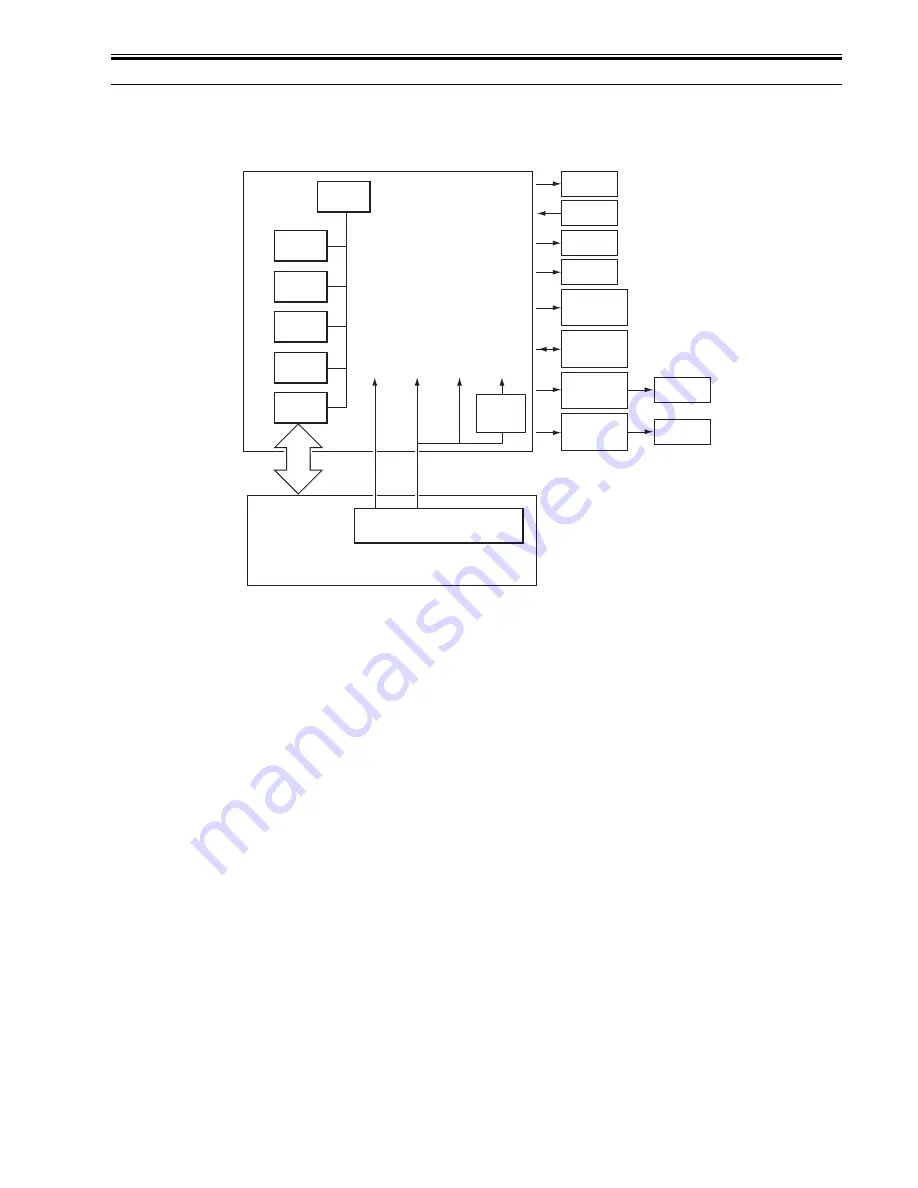
2.1.1 Overview of Electrical Circuit
0011-2223
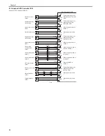
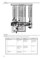
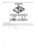
The machine's electrical mechanisms are controlled by the ADF controller PCB (microcomputer CPU). The CPU interprets signals from sensors and the host ma-
chine, and generates appropriate signals to drive such loads as motors and solenoids at such times as programmed in advance.
F-2-1
CPU
(Q1)
ROM
(IC1)
EEPROM
(IC2)
RAM
(Q4)
D/A
(Q9)
IPC
(Q2)
+5V
+24V
+5R
+24R
Power supply PCB
Copier
Solenoid
Clutch
Original
indicator
LED PCB
Sub tray PCB
Reversal
motor
driver PCB
Belt motor
driver PCB
Motor
Sensor
Motor
Motor
ADF controller PCB
DC5V
(Q65)
Содержание DADF-Q1
Страница 1: ...Aug 24 2007 Service Manual Feeder DADF Q1 ...
Страница 2: ......
Страница 6: ......
Страница 11: ...Chapter 1 Specifications ...
Страница 12: ......
Страница 14: ......
Страница 18: ......
Страница 19: ...Chapter 2 Functions ...
Страница 20: ......
Страница 22: ......
Страница 75: ...Chapter 3 Parts Replacement Procedure ...
Страница 76: ......
Страница 107: ...Chapter 4 Maintenance ...
Страница 108: ......
Страница 149: ...Chapter 5 Error Code ...
Страница 150: ......
Страница 151: ...Contents Contents 5 1 Service Error Code 5 1 5 1 1 E402 5 1 5 1 2 E404 5 1 5 1 3 E405 5 1 5 1 4 E410 5 1 5 1 5 E420 5 1 ...
Страница 152: ......
Страница 154: ......
Страница 155: ...Aug 24 2007 ...
Страница 156: ......

