Chapter 4
4-36
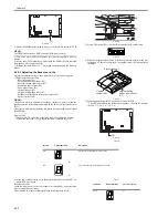
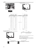
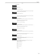
Separation Motor (M4), Clutch (CL) Drive
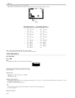
Press the push switch (SW2) on the ADF controller PCB to start it; another press will stop
it.
While in operation, each press on the push switch SW3 changes the speed of motor
rotation to 100mm/sec. (700 -> 100 mm/sec)
Manual Feed Operation
Place an original in the manual feed assembly, and press the push switch (SW2) on the
ADF controller PCB so that the original will be picked up and stopped.
Tray Pickup Arch Adjustment
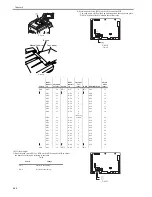
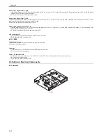
Press the push switch SW2 on the ADF controller PCB to start, and use the push switch
S23/SW4 to make adjustments. At the end, press the push switch SW2 to store the new
setting.
Reversal Arch adjustment
Press the push switch SW2 on the ADF controller PCB to start, and use the push switch
SW3/SW4 to make adjustments. At the end, press the push switch SW2 to store the new
setting.
Manual Feed Arch Adjustment
Press the push switch SW2 on the ADF controller PCB to start, and use the push switch
SW3/SW4 to make adjustments. At the end, press the push switch SW2 to store the new
setting.
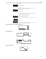
Feeding Belt Speed Adjustment (reproduction ratio in
stream reading)
Press the push switch SW2 on the ADF controller to start, and use the push switch SW3/
SW4 to make adjustments. At the end, press the push switch SW2 to store the new setting.
Reversal Speed Adjustment
Press the push switch SW2 on the ADF controller PCB to start, and use the push switch
SW3/SW4 to make adjustments. At the end, press the push switch SW2 to store the new
setting.
Original Stop Position Adjustment
Press the push switch SW2 on the ADF controller PCB to start, and use the push switch
SW3/SW4 to make adjustments. At the end, press the push switch SW2 to store the new
setting.
Manual Feed Original Stop Position Adjustment
Press the push switch SW2 on the ADF controller PCB to start, and use the push switch
SW3/SW4 to make adjustments. A the end, press the push switch SW2 to store the new
setting.
Sensor and Delivery Motor Auto Adjustment
Press the push switch SW2 on the ADF controller PCB. The operation will end
automatically.
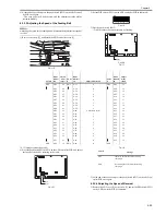
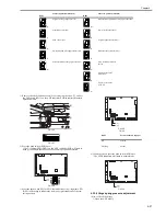
Jam History Indication
The jam history of the DADF will be indicated by DSP1 on the ADF controller PCB
(most recent three jams).
Software Version Indication
Press the push switch SW2 on the ADF controller PCB to indicate the version of the
software; another press will stop the indication.
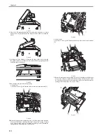
Separation Assembly Cleaning
Press the push switch (SW2) on the ADF controller PCB to rotate the registration roller;
another press will stop the operation.
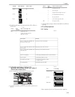
Setting Description
Содержание DADF-Q1
Страница 1: ...Aug 24 2007 Service Manual Feeder DADF Q1 ...
Страница 2: ......
Страница 6: ......
Страница 11: ...Chapter 1 Specifications ...
Страница 12: ......
Страница 14: ......
Страница 18: ......
Страница 19: ...Chapter 2 Functions ...
Страница 20: ......
Страница 22: ......
Страница 75: ...Chapter 3 Parts Replacement Procedure ...
Страница 76: ......
Страница 107: ...Chapter 4 Maintenance ...
Страница 108: ......
Страница 149: ...Chapter 5 Error Code ...
Страница 150: ......
Страница 151: ...Contents Contents 5 1 Service Error Code 5 1 5 1 1 E402 5 1 5 1 2 E404 5 1 5 1 3 E405 5 1 5 1 4 E410 5 1 5 1 5 E420 5 1 ...
Страница 152: ......
Страница 154: ......
Страница 155: ...Aug 24 2007 ...
Страница 156: ......

