Chapter 4
4-20
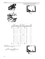
mm.
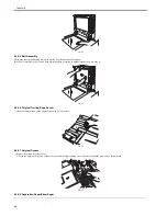
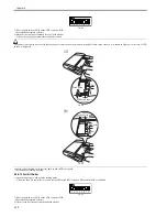
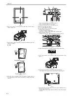
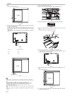
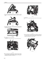
Then, close the DADF slowly.
F-4-97
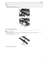
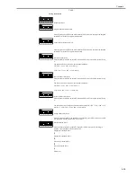
6) To adjust the original stop position, use the push switches SW3 and SW4
on the ADF controller PCB.
A single press on each switch will shift the original stop position by a dis-
tance of 0.5 mm. When the correct stop position is attained, press the push
switch (SW2).
- The original will be delivered, and the new position will be stored in
memory.
F-4-98
T-4-7
F-4-99
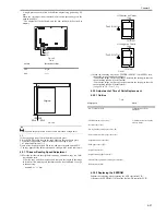
Holding down on the push switch will not cause more than a single shift.
EX
If the copy paper is stopped 12 mm from the copyboard glass,
Close the DADF slowly leaving the copy paper on the copyboard glass.
To shift the stop position 1 mm to the left, the following is true:
1 0.5 (adjustment interval) = 2
Hence, press the push switch SW4 twice, and then press the push switch
SW2.
- The copy paper will be delivered, and the new setting will be stored in
memory.
b. Pickup from the Manual Feed Tray
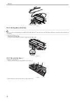
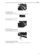
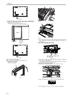
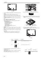
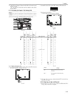
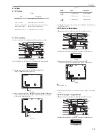
1) Remove the screw [1], and detach the ADF controller cover [2].
F-4-100
2) Set the DIP switch (SW1) on the ADF controller PCB as indicated.
F-4-101
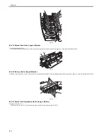
3) Open the manual feed tray, and place a single sheet of A4 or LTR copy
paper.
- Be sure to butt the copy paper against the rear.
F-4-102
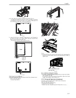
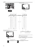
4) Press the push switch (SW2) on the ADF controller PCB once.
- A single press on the push switch (SW2) causes the original to be picked
up and stopped on the copyboard glass.
F-4-103
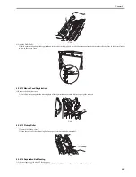
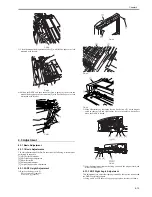
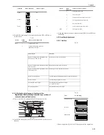
5) Open the DADF slowly, and check to make sure that D indicated is 11±1
mm.
Close the DADF slowly.
F-4-104
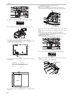
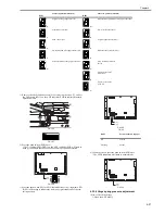
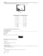
6) To adjust the original stop position, use the push switches SW3 and SW4
on the ADF controller PCB.
Switch
Direction of shift
SW3
Right
SW4
Left
D
Original
D=11±1mm
J1
J2
J5
J3
J6
J7
J8
J9
J10
J16
J15
J11
J14
IC8
J13
J12
J4
CB1
SW1
DSP1
SW4SW3SW2
Original
SW3
SW4
[1]
[2]
Butted.
Manual feed tray
Copy paper
J1
J2
J5
J3
J6
J7
J8
J9
J10
J16
J15
J11
J14
IC8
J13
J12
J4
CB1
SW1
DSP1
SW4SW3SW2
D
Original
D=11±1mm
Содержание DADF-Q1
Страница 1: ...Aug 24 2007 Service Manual Feeder DADF Q1 ...
Страница 2: ......
Страница 6: ......
Страница 11: ...Chapter 1 Specifications ...
Страница 12: ......
Страница 14: ......
Страница 18: ......
Страница 19: ...Chapter 2 Functions ...
Страница 20: ......
Страница 22: ......
Страница 75: ...Chapter 3 Parts Replacement Procedure ...
Страница 76: ......
Страница 107: ...Chapter 4 Maintenance ...
Страница 108: ......
Страница 149: ...Chapter 5 Error Code ...
Страница 150: ......
Страница 151: ...Contents Contents 5 1 Service Error Code 5 1 5 1 1 E402 5 1 5 1 2 E404 5 1 5 1 3 E405 5 1 5 1 4 E410 5 1 5 1 5 E420 5 1 ...
Страница 152: ......
Страница 154: ......
Страница 155: ...Aug 24 2007 ...
Страница 156: ......

