


CHAPTER 9 EXTERNALS / AUXILIARY MECHANISMS
9-22
COPYRIGHT © 1999 CANON INC. CANON CLC1120/1130/1150 REV.0 MAR. 1999 PRINTED IN JAPAN (IMPRIME AU JAPON)
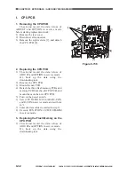
3) Disconnect the connector [3], and remove
the four screws [4]; then, detach the LCD
PCB.
Figure 9-713
4. Removing the Numeric Keypad
PCB
1) Remove the control panel PCB.
2) Remove the control panel fixing plate.
3) Remove the 13 screws [1], and remove the
pilot lamp assembly [2].
4) Remove the numeric keypad PCB [3].
Figure 9-714
[3]
[4]
[4]
[2]
[3]
[1]
[1]
[1]
Содержание CLC 1120
Страница 6: ......
Страница 20: ......
Страница 22: ......
Страница 48: ......
Страница 94: ......
Страница 96: ......
Страница 114: ......
Страница 134: ......
Страница 136: ......
Страница 152: ......
Страница 242: ......
Страница 346: ......
Страница 374: ......
Страница 376: ......
Страница 412: ......
Страница 452: ......
Страница 454: ......
Страница 517: ......
Страница 531: ...13 4 COPYRIGHT 1999 CANON INC CANON CLC1120 1130 1150 REV 0 MAR 1999 PRINTED IN JAPAN IMPRIME AU JAPON ...
Страница 881: ......
Страница 893: ......
Страница 895: ......
Страница 899: ......
Страница 901: ...0499S1 5 1 PRINTED IN JAPAN IMPRIME AU JAPON This publication is printed on 70 reprocessed paper ...


