CHAPTER 2 STANDARDS AND ADJUSTMENTS
2-44
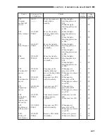
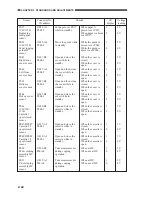
Sensor
PS37
(CLC1150)
Duplexing
inlet paper
sensor
PS40
(CLC1150)
Paper jogging
guide HP
sensor
PS41
Right front
cover sensor
PS42
Left front
cover sensor
PS43
Delivery
cover sensor
PS44
Pickup cover
sensor
PS46
(CLC120/
1130)
Cassette 1
open/closed
sensor
PS47/DPS47
Cassette 2/1
open/closed
sensor
PS48/DPS48
Cassette 3/1
open/closed
sensor
PS49
M developing
assembly HP
sensor
PS51
C developing
assembly HP
sensor
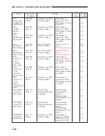
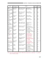
I/O
display
1
0
1
0
1
0
1
0
1
0
1
0
1
0
1
0
1
0
1
0
1
0
Connector No.
I/O address
J1022-A3
P002-2
J1022-A4
P009-4
J1027-B8
P004-1
J1027-A8
P004-2
J1027-B2
P004-0
J1007-B5
P004-3
J1020-B2
P008-3
J1017-A3
P008-2
J1018-A1
P008-1
J1016-B2
P00A-8
J1015-A3
P00A-9
When paper is
present over PS37,
When paper is absent
over PS37,
While the guide is
present over PS40,
While the guide is
absent over PS40,
When the cover is
closed,
When the cover is
open,
When the cover is
closed,
When the cover is
open,
When the cover is
closed,
When the cover is
open,
When the cover is
closed,
When the cover is
open,
When the cassette is
closed,
When the cassette is
open,
When the cassette is
closed,
When the cassette is
open,
When the cassette is
closed,
When the cassette is
open,
When at HP,
When not at HP,
When at HP,
When not at HP,
Put paper over PS37
while in standby.
Move the guide while
in standby.
Open and close the
cover while in
standby.
Open and then close
the cover while in
standby.
Open and then close
the cover while in
standby.
Open and close the
cover while in
standby.
Open and close the
cassette while in
standby.
Open and close the
cassette while in
standby.
Open and close the
cassette while in
standby.
Take measurements
during copying
operation.
Take measurements
during copying
operation.
Voltage
reading
5V
0V
5V
0V
5V
0V
5V
0V
5V
0V
5V
0V
5V
0V
5V
0V
5V
0V
5V
0V
5V
0V
Checks

