CHAPTER 2 STANDARDS AND ADJUSTMENTS
2-4
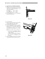
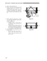
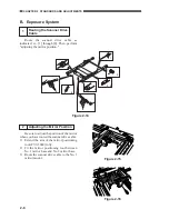
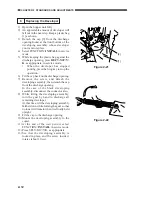
5) Slide out the transfer frame.
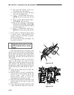
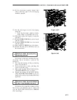
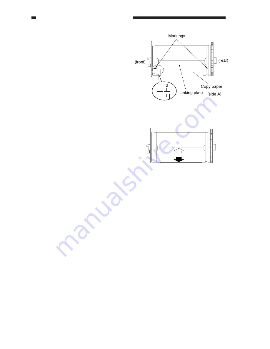
6) Place a ruler and copy paper against the
marking (Figure 2-7) etched to the
transfer drum ring (front, rear), and
measure the position d of the copy paper
in relation to the leading edge of the copy
paper. Perform this for both sides A and
B.
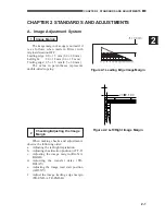
Figure 2-7
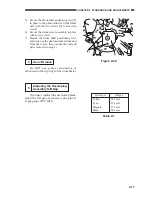
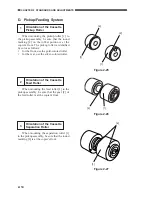
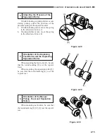
Figure 2-8
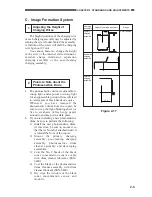
7) Make adjustments so that d is 0 ± 0.5 mm
in service mode (ADJUST>FEED-ADJ).
for side A:ATT-T-A
for side B: ATT-T-B
•
Changing ATT-T-A, ATT-T-B to '1'
will shift the point of attraction by
about 0.4 mm.
•
A higher setting will delay the start of
attraction (in the direction of the black
arrow) while a lower setting advances
it (in the direction of the white arrow).
8) After adjustment, turn off and then on the
power switch.
•
Keep in mind that copies made in
normal mode will be black if you
forget to turn off and then on the
power switch.
(front)
(rear)


