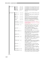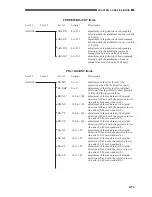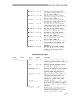
4-77
CHAPTER 4 SERVICE MODE
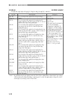
Level 3
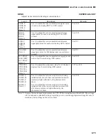
ADJ-S
(Note 1)
ADJ-J
(Note 1)
Remarks
0 to 45
(0 to 4.8 mm)
Unit: about 0.107 mm
0 to +190
Unit: about 0.1 msec
Description
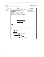
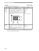
Use it to fine-adjust the position at which data is
collected for shading correction from the standard
white plate.
• Unit: number of steps from the stepping motor
• Scratches or dirt on the standard plate can cause
vertical white lines on copies. To correct the
problem, shift the point of measurement using this
item.
Use it to adjust the period of acceleration for the
original scanner motor.
(front)
Point of measurement
Standard white plate
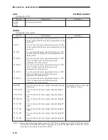
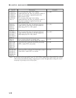
Note
1
: Execute this mode upon replacement of a PCB or initialization of the RAM. The settings will
be returned to standard settings, requiring you to enter the appropriate settings. Be sure to
record any new settings on the service label.
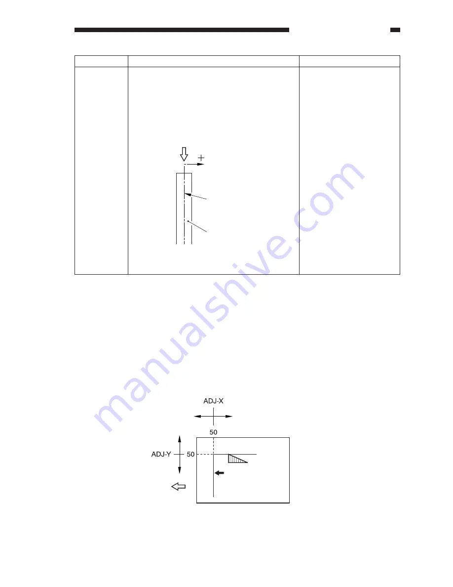
Adjusting the Image Read Start Position
Be sure to check the present point of attraction before starting the work.
1) Turn off the original detection mechanism before starting service mode.
2) Bring up the ADJ-XY screen, and press the Copy Start key.
•
Appropriate copying mode will automatically be set, and a copy is made with a shift of
about 50 mm as shown.
3) If any part of the image is missing, decrease the setting of ADJ-X, ADJ-Y.
4) If an area outside the image is copied, increase the setting of ADJ-X, ADJ-Y.
Figure 4-11

