COPYRIGHT © 2001 CANON INC. CANON CLC1000/1000S/3100 REV.2 MAY 2001 PRINTED IN JAPAN (IMPRIME AU JAPON)
3-135
3. OPERATION AND TIMING
b.
Cassette Lifter Operation
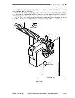
Figures 3-605 and -606 show outlines of cassette lifter operation.
When the cassette is set in the copier, the pick-up roller lowers and the lifter detecting lever leaves the
lifter sensor.
The condition turns on the cassette lifer motor, thereby raising the lifter. The cassette lifter motor stops
where the cassette lifter sensor can detect the top surface of the stack of paper on the lifter.
When paper runs out and the paper detecting lever leaves the paper sensor, the message ‘ADD
PAPER’ will be indicated on the control panel.
The notations of the lifter motor, cassette lifter sensor, and cassette paper sensor used for the cassettes
1 and 2 are as shown in Table 3-606.
Table 3-606
Figure 3-605
Cassette 1
M16
PS24
PS23
Cassette
Name
Cassette lifter
motor
Cassette lifter
sensor
Cassette paper
sensor
Cassette 2
M17
PS27
PS28
M
Lifter push-up
plate
Cassette lifter motor
Cassette
Separation roller
Feeding roller
Lifter sensor
Lifter detecting lever
Paper detecting lever
Cassette paper sensor
Lifter
Paper
Pick-up roller
Содержание 1000S
Страница 12: ......
Страница 30: ......
Страница 44: ......
Страница 86: ......
Страница 254: ......
Страница 372: ......
Страница 374: ......
Страница 418: ......
Страница 438: ......
Страница 442: ......
Страница 754: ......
Страница 764: ......
Страница 766: ......
Страница 840: ...0501GR PRINTED IN JAPAN IMPRIME AU JAPON This publication is printed on 100 reprocessed paper ...


