background image

19

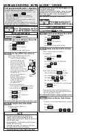
La prima codifica deve essere effettuata mantenendo i jumper posizionati

per i canali 1 e 2 come da fig. A; per eventuali e successive impostazioni

su canali diversi vedi fig. B

The first encoding operation must be carried out whilst keeping the jumpers

positioned for channels 1 and 2 as per fig. A; see fig. B for any subsequent

settings on different channels.

La première codification doit être effectuée en maintenant les cavaliers

en position pour les canaux 1 et 2, comme d'après la fig. A; pour des

saisies successives éventuelles sur des canaux différents, voir fig. B

Für die erste Codierung muß der Jumper auf den Kanälen 1 und 2

positioniert bleiben (siehe Abb. A). Für eventuelle weitere oder spätere

Einstellungen auf anderen Kanälen halten Sie sich bitte an Abb. B.

La primera codificación tiene que efectuarse manteniendo los jumper

conectados para los canales 1 y 2 como se ilustra en la fig. A; para

planteamientos posteriores en canales distintos ver la fig. B

T262L/M  -  T302L/M

T2622M  -  T3022M

2°  codice/

codice/codice/codice/codice

1°  codice/

codice

codice/

codice/codice

CODIFICA TRASMETTITORI - 

TRANSMITTER ENCODING - CODIFICATION DES EMETTEURS

CODIERUNG DER SENDER - CODIFICACIÓN TRANSMISORES

P1

P2

J

P1=CH1
P2=CH2

fig. A

fig. B

P1=CH1 - P2=CH4

P1=CH1 - P2=CH3

P1=CH3 - P2=CH2

P1=CH3 - P2=CH4

ON

OFF

P1

P2

P3=CH1
P4=CH2

J

P1

P2

P3

P4

P1=CH1
P2=CH2

J

P1

P2

P3

P4

J

P1=CH1 - P2=CH2
P3=CH3 - P4=CH4

T264L/M  -  T304L/M

Содержание U 8700

Страница 1: ...ANTA CON MOTORIDUTTORE F500 COMPLETE SET FOR POWERING PEDESTRIAN AND OR DRIVEWAY GATES HAVINGTWO SWINGING GATE WINGS WITH MAXIMUM WIDTH OF 1 60 M EACH WITH F500 GEARMOTOR SET COMPLET POUR L AUTOMATIS...

Страница 2: ...MENSIONES M XIMAS i 230 mm max con apertura a 90 with 90 opening angle avec ouverture 90 mit 90 ffnungwinkel con apertura a 90 Larghezza anta Width of gate wing Largeur du vantail Torbreite Ancho hoja...

Страница 3: ...T MAXIMUM POWER CONSUMPTION DUTY CICLE MAXIMUM TORQUE REDUCTION RATIO MOTOR DUCTEUR DEGR DE PROTECTION POIDS ALIMENTATION COURANT MAXIMALE PUISSANCE MAXIMALE ABSORBEE INTERMITTENCE DE TRAVAIL COUPLE M...

Страница 4: ...riebe motor Flansch an der Wand oder am Pfosten befestigen und bei Verwedung des Getrie bemotor F500 die entsprechende Befesti gungsvorrichtung am Tor anbringen 1 Trazar los ejes y las dimensiones del...

Страница 5: ...ung entfernen 3 Remove the cover at the bottom of the gear motor 4 Fissare il moto riduttore alla flangia mediante le quattro viti in dotazione Fissare la calotta su periore 4 Using the four screws pr...

Страница 6: ...ectrique don ner de la tension au motor ducteur en fer meture et fixer le bras l aide du boulon sans t te M6 C Fixer la calotte inf rieure 5 Den Gelenkarm B an der mittleren Buchse anbringen die fest...

Страница 7: ...o re solo apre per trasmettitore REGOLAZIONI Tempo chiusura automatica Tempo apertura parziale e ritardo chiusura del 2 motore Tempo lavoro DESCRIPTION The ZL150 control panel is suitable for controll...

Страница 8: ...n f r Fl geltore der Serie FLEX mit einer Versorgungsspannung von 24V DC einer Leistung von max 48 W und einer Frequenz von 50 60 Hz Entwurf und Konstruktion sind von der CAME S p A sie entspricht den...

Страница 9: ...or parado puerta cerrada abierta o en posici n semi abierta obtenida a trav s de un comando de stop total anula cualquier funci n del transmisor o del bot n en caso de obst culo detectado por los disp...

Страница 10: ...e ligne 5A 3 Fusible bo tier 1 6A 4 LED de signalisation 5 Boutons poussoir m morisation code radio 6 Trimmer de r glage temps de fonctionnement 7 Trimmer de r glage fermeture automatique 8 Trimmer de...

Страница 11: ...se with button 2 7 and radio control AF board inserted enabled 3 ON Only opening with radio control AF board inserted enabled 3OFF disabled 4 ON Pre flashing opening and closing enabled 4OFF disabled...

Страница 12: ...s bornes 2 CX activado si no utiliza los dispositivos en 2 CX coloque el dip 8 en ON 9 OFF Reapertura en la fase de cierre conecte el dispositivo de seguridad a los bornes 2 C1 activado si no se utili...

Страница 13: ...hing light Sortie 24V c a 25W max en mouvement ex branchement clignotant Ausgang 24V Wechselstrom 25W max in Bewegung z B Blinker Anschlu Salida de 24V 25W max a c en movimiento p ej conexi n l mpara...

Страница 14: ...ber Motor 2 Tecla N O para apertura parcial apertura del 2 motor Pulsante chiude N O N O Pushbutton close Bouton poussoir fermeture N O Taste Schlie en Arbeitskontakt Pulsador de cierre N O Contatto...

Страница 15: ...stop partiel Runekontakt Teilstop Contacto N C parada parcial 2 1 3 4 5 6 7 8 9 10 O N 2 1 3 4 5 6 7 8 9 10 O N 8 OFF 10 OFF 8 OFF 10 ON N B Tutti i contatti e pulsanti N C non collegati ad accessori...

Страница 16: ...ange the code on your transmitters in the future simply repeat the procedure described above FRAN AIS FRAN AIS FRAN AIS FRAN AIS FRAN AIS PROCEDER COMME SUIT POUR UTILISER LA RADIOCOMMANDE A Couper la...

Страница 17: ...1 Efectuar el mismo procedimiento con la tecla CH2 asoci ndola a otra tecla del transmisor fig 2 CH1 Canal para mandos dirigidos a una funci n del cuadro de mandos solo abrir abrir cerrar o bien abri...

Страница 18: ...mo impulso un doppio suono confermer l avvenuta registrazione Press P1 or P2 in sequence in order to register the code at the tenth pulse a double beep will confirm that registration has occurred appu...

Страница 19: ...der Jumper auf den Kan len 1 und 2 positioniert bleiben siehe Abb A F r eventuelle weitere oder sp tere Einstellungen auf anderen Kan len halten Sie sich bitte an Abb B La primera codificaci n tiene...

Страница 20: ...instructions sur le sachet de l emballage Siehe Anleitungen auf der Packung ver instrucciones en el embalaje T432S T434M T314M impostare solo il codice set code only ne saisir que le code Stellen Sie...

Отзывы: