


45
Proprietary Information: Not for use or disclosure except by written agreement with Calix.
© Calix. All Rights Reserved.
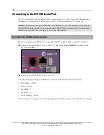
To wire out the E7-2 subscriber line interfaces
1.
Route the 25-pair equipment interface cables (RJ-21 connectors) to the rear of the E7-2
shelf.
2.
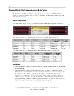
On the rear of the E7-2, terminate the interface cable(s) for slot 1 to the RJ-21 connector
labeled
P1
or
P2
and the interface cable(s) for slot 2 to the RJ-21 connector labeled
P3
or
P4
, as required for the installed line card(s). See
Cable assignments
above for more
information.
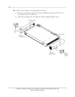
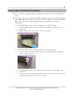
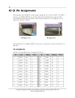
For an RJ-21 male connector with a 110-degree exit, do the following:
a.
Insert the RJ-21 male connector into the female connector on the back of the
E7-2 shelf.
b.
Tighten the screws on each side to secure the connector.
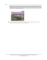
For an RJ-21 male connector with a 90-degree exit, do the following:
a.
Using a 4-40 screw, attach a cable tie mount to the right side of the shelf RJ-21
female connector as shown.
b.
Insert the RJ-21 male connector into the female connector on the back of the
E7-2 shelf.
c.
Secure the connector by tightening the screw at the bottom of the connector and
attaching a tie wrap at the top of the connector.
Содержание E7-2
Страница 1: ...Calix E7 2 Installation Guide May 2013 220 00320 Rev 13...
Страница 2: ......


