


40
Proprietary Information: Not for use or disclosure except by written agreement with Calix.
© Calix. All Rights Reserved.
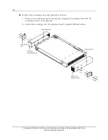
To provide timing relays to one or more additional collocated E7-2 units, you can wire the
E7-2 external timing output interface as described below.
To wire the BITS timing output interface
1.
Get up to two 24 AWG shielded 2-wire cables of sufficient length to reach the next E7-2
shelf. Use one cable to provide a single link (A only), or two cables for a redundant link
(A + B).
Note:
You can use the optional Calix-supplied BITS daisy-chain cable instead. See the
note after Step 4 for installation instructions.
2.
Strip approximately one inch (2.54 cm) of insulation from the wire ends.
3.
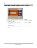
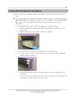
Wire the E7-2 external timing output as follows:
a.
Connect the timing wires to the E7-2 BITS
OUT (A)
output position:
Wrap the positive (tip) wire to the
TIP+
pin.
Wrap the negative (ring) wire to the
RNG-
pin.
b.
To provide a redundant timing link to the next E7-2, repeat Step 3a to wire the E7-2
BITS
OUT (B)
position, as required.
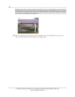
4.
Route and dress the timing output cable to next E7-2 and connect per the input wiring
procedure above.
Note:
If you are using the Calix-supplied BITS daisy-chain cable, connect the
WW Pins
Out
end to the BITS
OUT
pins on the upstream E7-2 unit, and connect the
WW Pins
In
end to the BITS
IN
pins on downstream unit. Repeat for each additional daisy-
chained E7-2 unit.
Содержание E7-2
Страница 1: ...Calix E7 2 Installation Guide May 2013 220 00320 Rev 13...
Страница 2: ......


